Toyota Tacoma (2015-2018) Service Manual: Blind Spot Monitor Main Switch
Components
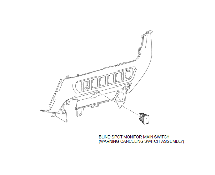
COMPONENTS
ILLUSTRATION
Removal
REMOVAL
PROCEDURE
1. REMOVE INSTRUMENT PANEL LOWER CENTER FINISH PANEL
(See page .gif) )
)
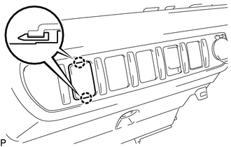
2. REMOVE BLIND SPOT MONITOR MAIN SWITCH (WARNING CANCELING SWITCH ASSEMBLY)
|
(a) Disengage the 2 claws to remove the blind spot monitor main switch (warning canceling switch assembly). |
|
Inspection
INSPECTION
PROCEDURE
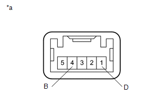
1. INSPECT BLIND SPOT MONITOR MAIN SWITCH (WARNING CANCELING SWITCH ASSEMBLY)
|
(a) Measure the resistance according to the value(s) in the table below. Text in Illustration
Standard Resistance:
If the result is not as specified, replace the blind spot monitor main switch (warning canceling switch assembly). |
|
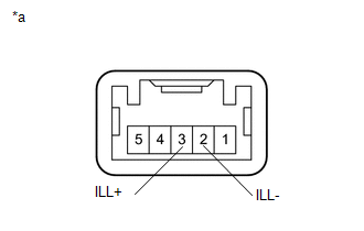
(b) Check that the switch illuminates.
|
(1) Apply battery voltage to the blind spot monitor main switch (warning canceling switch assembly) and check that the switch illuminates. Text in Illustration
OK:
If the result is not as specified, replace the blind spot monitor main switch (warning canceling switch assembly). |
|
(c) Check that the switch indicator operates.
|
(1) Apply battery voltage to the blind spot monitor main switch (warning canceling switch assembly) and check that the switch indicator operates. Text in Illustration
OK:
If the result is not as specified, replace the blind spot monitor main switch (warning canceling switch assembly). |
|
Installation
INSTALLATION
PROCEDURE
1. INSTALL BLIND SPOT MONITOR MAIN SWITCH (WARNING CANCELING SWITCH ASSEMBLY)
(a) Engage the 2 claws to install the blind spot monitor main switch (warning cancel switch assembly).
2. INSTALL INSTRUMENT PANEL LOWER CENTER FINISH PANEL
(See page .gif) )
)


Other materials:
How To Proceed With Troubleshooting
CAUTION / NOTICE / HINT
Techstream can be used in steps 3, 6, 9 and 12.
PROCEDURE
1.
VEHICLE BROUGHT TO WORKSHOP
NEXT
2.
CUSTOMER PROBLEM ANALYSIS
...
Transmission Fluid Temperature Sensor "B" Circuit Low Input (P2742,P2743)
DESCRIPTION
The No. 2 ATF temperature sensor is installed in the transmission valve body
assembly.
If the ECM detects an abnormally high ATF temperature near this sensor, it illuminates
the warning indicator.
HINT:
The temperature of ATF easily rises when towing, climbing hills, in
...
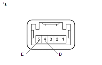
Terminals Of Ecu
TERMINALS OF ECU
1. CHECK 4 WHEEL DRIVE CONTROL ECU
Text in Illustration
*a
Component with harness connected
(4 Wheel Drive Control ECU)
-
-
(a) Measure the resistance and voltage according to the value(s) in the table
below.
...
