Toyota Tacoma (2015-2018) Service Manual: Front Passenger Side Door ECU Communication Stop (B2322)
DESCRIPTION
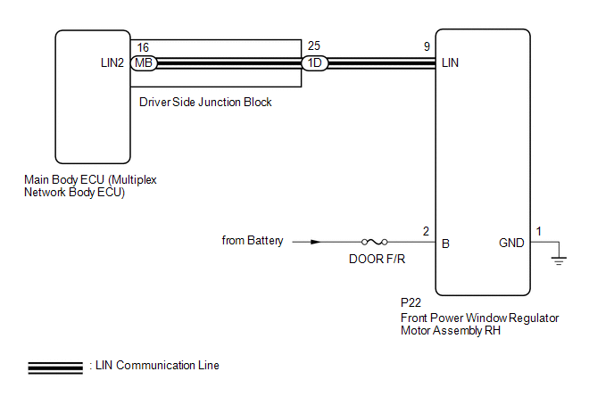
This DTC is stored when LIN communication between the front power window regulator motor assembly RH and main body ECU (multiplex network body ECU) stops for 10 seconds or more.
|
DTC No. |
DTC Detection Condition |
Trouble Area |
|---|---|---|
|
B2322 |
No communication between front power window regulator motor assembly RH and main body ECU (multiplex network body ECU) for 10 seconds or more. |
|
WIRING DIAGRAM
CAUTION / NOTICE / HINT
NOTICE:
- Inspect the fuses for circuits related to this system before performing the following inspection procedure.
- If the main body ECU (multiplex network body ECU) is replaced, refer
to Registration (See page
.gif) )
) - When a power window regulator motor assembly is replaced or removed
and reinstalled, it requires initialization (See page
).
PROCEDURE
|
1. |
INSPECT DRIVER SIDE JUNCTION BLOCK |
(a) Remove the driver side junction block (See page
).
(b) Remove the main body ECU (multiplex network body ECU) from the driver side junction block.
(c) Measure the resistance according to the value(s) in the table below.
.png)
Standard Resistance:
|
Tester Connection |
Condition |
Specified Condition |
|---|---|---|
|
1D-25 - MB-16 (LIN2) |
Always |
Below 1 Ω |
|
*a |
Component without harness connected (Driver Side Junction Block) |
- |
- |
HINT:
This inspection is to check the LIN line in the driver side junction block that connects the wire harness to the built-in main body ECU (multiplex network body ECU).
| NG | .gif) |
REPLACE DRIVER SIDE JUNCTION BLOCK |
|
.gif)
|
2. |
CHECK HARNESS AND CONNECTOR (DRIVER SIDE JUNCTION BLOCK - FRONT POWER WINDOW REGULATOR MOTOR ASSEMBLY RH) |
(a) Disconnect the 1D driver side junction block connector.
(b) Disconnect the P22 front power window regulator motor assembly RH connector.
(c) Measure the resistance according to the value(s) in the table below.
Standard Resistance:
|
Tester Connection |
Condition |
Specified Condition |
|---|---|---|
|
1D-25 - P22-9 (LIN) |
Always |
Below 1 Ω |
|
1D-25 or P22-9 (LIN) - Body ground |
Always |
10 kΩ or higher |
| NG | |
REPAIR OR REPLACE HARNESS OR CONNECTOR |
|
|
3. |
CHECK HARNESS AND CONNECTOR (FRONT POWER WINDOW REGULATOR MOTOR ASSEMBLY RH - POWER SOURCE CIRCUIT) |
(a) Disconnect the P22 front power window regulator motor assembly RH connector.
(b) Measure the voltage according to the value(s) in the table below.
Standard Voltage:
|
Tester Connection |
Condition |
Specified Condition |
|---|---|---|
|
P22-2 (B) - P22-1 (GND) |
Always |
11 to 14 V |
(c) Measure the resistance according to the value(s) in the table below.
Standard Resistance:
|
Tester Connection |
Condition |
Specified Condition |
|---|---|---|
|
P22-1 (GND) - Body ground |
Always |
Below 1 Ω |
| NG | |
REPAIR OR REPLACE HARNESS OR CONNECTOR |
|
|
4. |
REPLACE FRONT POWER WINDOW REGULATOR MOTOR ASSEMBLY RH |
(a) Replace the front power window regulator motor assembly RH.
|
|
5. |
CHECK DTC OUTPUT |
(a) Clear the DTCs (See page ).
(b) Check for DTCs.
OK:
DTC B2322 is not output.
| OK | |
END (FRONT POWER WINDOW REGULATOR MOTOR ASSEMBLY RH WAS DEFECTIVE) |
| NG | |
REPLACE MAIN BODY ECU (MULTIPLEX NETWORK BODY ECU) |
 Lost Communication with Power Source Control (B278C)
DESCRIPTION
DTC No.
DTC Detection Condition
Trouble Area
B278C
An internal malfunction occurs in the certification ECU (smart key ECU
...

Other materials:
Diagnosis System
DIAGNOSIS SYSTEM
1. DESCRIPTION
(a) When troubleshooting OBD II (On-Board Diagnostics) vehicles, an OBD II scan
tool (complying with SAE J1978) must be connected to the DLC3 (Data Link Connector
3) of the vehicle. Various data in the vehicle ECM (Engine Control Module) can be
then read.
(b) ...
Precaution
PRECAUTION
1. IGNITION SWITCH EXPRESSION
(a) The type of ignition switch used on this model differs depending on the specifications
of the vehicle. The expressions listed in the table below are used in this section.
Expression
Ignition Switch (Position)
Engine S ...
Clearance Warning Ecu
Components
COMPONENTS
ILLUSTRATION
Installation
INSTALLATION
PROCEDURE
1. INSTALL CLEARANCE WARNING ECU ASSEMBLY
(a) Connect the connector.
(b) Engage the 2 guides to install the clearance warning ECU assembly.
(c) Install the 2 screws.
2. INSTALL AIR CONDITIONING CONTROL ASSEMBLY (f ...
