Components
COMPONENTS
ILLUSTRATION
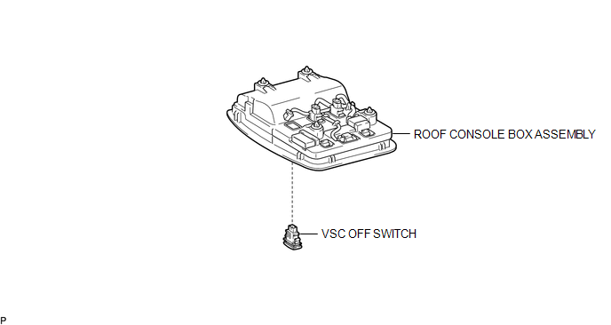
Inspection
INSPECTION
PROCEDURE
1. INSPECT VSC OFF SWITCH
(a) Check the resistance.
|
(1) Measure the resistance according to the value(s) in the table below. Text in Illustration
Standard Resistance:
If the value is not as specified, replace the VSC off switch. |
|
Removal
REMOVAL
PROCEDURE
1. REMOVE ROOF CONSOLE BOX ASSEMBLY
(See page
)
2. REMOVE VSC OFF SWITCH
(a) Disconnect the VSC off switch connector.
|
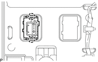
(b) Disengage the 2 claws and remove the VSC off switch from the roof console box assembly. |
|
Installation
INSTALLATION
PROCEDURE
1. INSTALL VSC OFF SWITCH
(a) Engage the 2 claws to install the VSC off switch into the roof console box assembly.
(b) Connect the VSC off switch connector.
2. INSTALL ROOF CONSOLE BOX ASSEMBLY
(See page
)
VSC OFF Switch Circuit
Parking BrakeData Signal Circuit between Radio Receiver and Stereo Jack Adapter
DESCRIPTION
The No. 1 stereo jack adapter assembly sends the sound data signal or image data
signal from a USB device to the radio and display receiver assembly via this circuit.
WIRING DIAGRAM
PROCEDURE
1.
CHECK HARNESS AND CONNECTOR (RADIO AND DISPLAY RECEIVER ASSEMB ...
System Diagram
SYSTEM DIAGRAM
Communication Table
Sender
Receiver
Signal
Communication Method
Power window regulator master switch assembly*1
Main Body ECU (Multiplex Network Body ECU)
Door control switch signal
...
Inspection
INSPECTION
PROCEDURE
1. INSPECT REAR SPEAKER ASSEMBLY (w/o Amplifier Box Speaker Assembly)
(a) Measure the resistance according to the value(s) in the table below.
Standard resistance:
Tester Connection
Condition
Specified Condition
1 - 2
...