Toyota Tacoma (2015-2018) Service Manual: Vacuum Warning Switch
Components
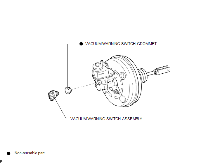
COMPONENTS
ILLUSTRATION
On-vehicle Inspection
ON-VEHICLE INSPECTION
PROCEDURE
1. INSPECT BRAKE FLUID LEVEL IN RESERVOIR
2. INSPECT BRAKE BOOSTER ASSEMBLY
.gif)
3. INSPECT VACUUM WARNING SWITCH ASSEMBLY
(a) Start the engine and stop it after 1 or 2 minutes.
(b) Disconnect the connector from the vacuum warning switch assembly.
(c) Measure the resistance of the vacuum warning switch assembly.
Standard Resistance:
10 kΩ or higher
(d) With the engine stopped, depress the brake pedal several times to release vacuum from the brake booster assembly, and measure the resistance of the vacuum warning switch assembly.
Standard Resistance:
Below 1 Ω
(e) Connect the connector to the vacuum warning switch assembly.
Installation
INSTALLATION
PROCEDURE
1. INSTALL VACUUM WARNING SWITCH GROMMET
(a) Install a new vacuum warning switch grommet to the brake booster assembly.
2. INSTALL VACUUM WARNING SWITCH ASSEMBLY
(a) Install the vacuum warning switch assembly to the brake booster assembly as shown in the illustration.
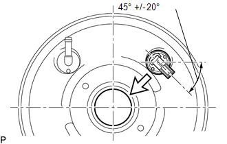 Text in Illustration
.png) |
Center of the Brake Booster Assembly |
(b) Connect the connector to the vacuum warning switch assembly.
Removal
REMOVAL
PROCEDURE
1. REMOVE VACUUM WARNING SWITCH ASSEMBLY
(a) Disconnect the connector from the vacuum warning switch assembly.
(b) Remove the vacuum warning switch assembly from the brake booster assembly.
2. REMOVE VACUUM WARNING SWITCH GROMMET
(a) Remove the vacuum warning switch grommet from the brake booster assembly.
 Vacuum Pump
Components
COMPONENTS
ILLUSTRATION
Installation
INSTALLATION
PROCEDURE
1. INSTALL VACUUM PUMP ASSEMBLY
(a) Apply engine oil to the 2 O-rings on the vacuum pump assembly.
(b) Apply engine ...

Other materials:
Identification Information
Vehicle Identification And Serial Numbers
VEHICLE IDENTIFICATION AND SERIAL NUMBERS
1. VEHICLE IDENTIFICATION NUMBER
(a) The vehicle identification number is stamped on the vehicle body and on the
certification label, as shown in the illustration.
A:
Vehicle Identification Number
B:
C ...
Lost Communication with ECM / PCM "A" (U0100,U0125,U0126,U0129)
DESCRIPTION
These DTCs are stored when a communication malfunction occurs between ECUs that
perform pre-collision system control.
DTC No.
Detection Item
DTC Detection Condition
Trouble Area
U0100
Lost Communication with ECM ...
Installation
INSTALLATION
PROCEDURE
1. INSTALL FRONT CRANKSHAFT OIL SEAL
(a) Using SST and a hammer, tap in a new oil seal until its surface is
flush with the timing chain cover assembly edge.
SST: 09223-22010
SST: 09506-35010
NOTICE:
Keep the lip free from foreign matt ...
