Toyota Tacoma (2015-2018) Service Manual: Terminals Of Ecu
TERMINALS OF ECU
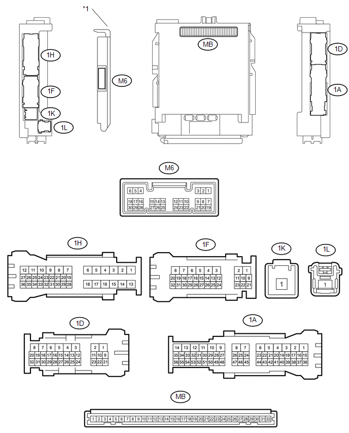
1. CHECK MAIN BODY ECU (MULTIPLEX NETWORK BODY ECU) AND DRIVER SIDE JUNCTION BLOCK
(a) Disconnect the main body ECU (multiplex network body ECU) connectors.
 Text in Illustration
|
*1 |
Main Body ECU (Multiplex Network Body ECU) |
- |
- |
(b) Measure the voltage and resistance according to the value(s) in the table below.
HINT:
Measure the values on the wire harness side with the connectors disconnected.
|
Tester Connection |
Wiring Color |
Terminal Description |
Condition |
Specified Condition |
|---|---|---|---|---|
|
MB-11(GND1) - Body ground |
- |
Ground |
Always |
Below 1 öˋ |
|
MB-31 (BECU) - Body ground |
- |
Battery power supply |
Always |
11 to 14 V |
|
MB-30 (ACC) - Body ground |
- |
ACC power supply |
Ignition switch ACC |
11 to 14 V |
|
MB-30 (ACC) - Body ground |
- |
ACC power supply |
Ignition switch off |
Below 1 V |
|
MB-32 (IG) - Body ground |
- |
IG power supply |
Ignition switch ON |
11 to 14 V |
|
MB-32 (IG) - Body ground |
- |
IG power supply |
Ignition switch off |
Below 1 V |
|
MB-14 (TRLY) - Body ground |
- |
Supply battery to taillight relay drive |
Always |
11 to 14 V |
If the result is not as specified, there may be a malfunction in the wire harness.
(c) Reconnect the main body ECU (multiplex network body ECU) connectors.
(d) Measure the voltage and check for pulses according to the value(s) in the table below.
|
Tester Connection |
Wiring Color |
Terminal Description |
Condition |
Specified Condition |
|---|---|---|---|---|
|
M6-27 (FRCY) - Body ground |
LG - Body ground |
Front door courtesy light switch RH input |
Front door RH open |
Below 1 V |
|
M6-27 (FRCY) - Body ground |
LG - Body ground |
Front door courtesy light switch RH input |
Front door RH open |
11 to 14 V |
|
M6-6 (FLCY) - Body ground |
Y - Body ground |
Front door courtesy light switch LH input |
Front door LH open |
Below 1 V |
|
M6-6 (FLCY) - Body ground |
Y - Body ground |
Front door courtesy light switch LH input |
Front door LH closed |
11 to 14 V |
|
1H-36 (LCTY) - Body ground |
P - Body ground |
Rear door courtesy light switch LH input*1 Upper access panel lock assembly LH input*2 Lower access panel lock assembly LH input*2 |
Rear door LH open |
Below 1 V |
|
1H-36 (LCTY) - Body ground |
P - Body ground |
Rear door courtesy light switch LH input*1 Upper access panel lock assembly LH input*2 Lower access panel lock assembly LH input*2 |
Rear door LH closed |
Pulse generation |
|
1D-30 (RCTY) - Body ground |
V - Body ground |
Rear door courtesy light switch RH input*1 Upper access panel lock assembly RH input*2 Lower access panel lock assembly RH input*2 |
Rear door RH open |
Below 1 V |
|
1D-30 (RCTY) - Body ground |
V - Body ground |
Rear door courtesy light switch RH input*1 Upper access panel lock assembly RH input*2 Lower access panel lock assembly RH input*2 |
Rear door RH closed |
Pulse generation |
|
1D-11 (LSFL) - Body ground |
P - Body ground |
Front door LH unlock detection switch input |
Front door LH unlocked |
Below 1 V |
|
1D-11 (LSFL) - Body ground |
P - Body ground |
Front door LH unlock detection switch input |
Ignition switch off, all doors closed and front door LH locked |
Pulse generation |
|
1D-24 (LSFR) - Body ground |
GR - Body ground |
Front door RH unlock detection switch input |
Front door RH unlocked |
Below 1 V |
|
1D-24 (LSFR) - Body ground |
GR - Body ground |
Front door RH unlock detection switch input |
Ignition switch off, all doors closed and front door RH locked |
Pulse generation |
|
1A-41 (LSR) - Body ground*1 |
Y - Body ground |
Rear door RH unlock detection switch input |
Rear door RH or LH unlocked |
Below 1 V |
|
1A-41 (LSR) - Body ground*1 |
Y - Body ground |
Rear door RH unlock detection switch input |
Ignition switch off, all doors closed and rear door RH and LH locked |
Pulse generation |
|
1H-27 (LSR) - Body ground*1 |
L - Body ground |
Rear door LH unlock detection switch input |
Rear door LH or RH unlocked |
Below 1 V |
|
1H-27 (LSR) - Body ground*1 |
L - Body ground |
Rear door LH unlock detection switch input |
Ignition switch off, all doors closed and rear door LH and RH locked |
Pulse generation |
|
1D-31 (KSW) - Body ground*3 |
G - Body ground |
Key unlock warning switch input |
Key in ignition key cylinder |
Below 1 V |
|
No key in ignition key cylinder |
11 to 14 V or Pulse generation |
|||
|
M6-15 (IND) - Body ground*3 |
V - Body ground |
Security indicator illumination |
Security indicator light illuminates (It illuminates only for 57 seconds in alarm sounding state.) |
3 to 10 V |
|
1F-31 (SH) - Body ground |
L - Body ground |
Security horn drive |
Security horn sounding (Theft deterrent system is in alarm sounding state) |
Pulse generation (Below 1 V ã ã 11 to 14 V) |
|
1F-26 (HORN) - Body ground |
L - Body ground |
Vehicle horn drive |
Vehicle horns sounding (Theft deterrent system is in alarm sounding state) |
Pulse generation (Below 1 V ã ã 11 to 14 V) |
|
1F-28 (HRLY) - Body ground |
W - Body ground |
Headlight relay driver output |
Headlight blinks (Theft deterrent system is in alarm sounding state) |
Pulse generation (Below 1 V ã ã 11 to 14 V) |
|
1D-29 (ILE) - Body ground |
BE - Body ground |
Interior light driver output |
Interior light illuminates (Theft deterrent system is in alarm sounding state) |
11 to 14 V |
|
M6-2 (UL3) - Body ground |
G - Body ground |
Driver door key-linked unlock input |
Driver door key cylinder turned to neutral position ã on (unlock) |
Pulse generation ã Below 1 V |
|
M6-29 (L2) - Body ground |
SB - Body ground |
Driver door key-linked lock input |
Driver door key cylinder turned to neutral position ã on (lock) |
Pulse generation ã Below 1 V |
- *1: for Double Cab
- *2: for Access Cab
- *3: w/o Smart Key System
If the result is not as specified, the main body ECU (multiplex network body ECU) may have a malfunction.
 Problem Symptoms Table
PROBLEM SYMPTOMS TABLE
HINT:
Troubleshooting of the theft deterrent system is based on the premise
that the power door lock control system, wireless door lock control system*1
and sm ...
 Data List / Active Test
DATA LIST / ACTIVE TEST
1. DATA LIST
HINT:
Using the Techstream to read the Data List allows the values or states of switches,
sensors, actuators and other items to be read without removing any p ...
Other materials:
Data List / Active Test
DATA LIST / ACTIVE TEST
1. READ DATA LIST
HINT:
Using the Techstream to read the Data List allows the values or states of switches,
sensors, actuators and other items to be read without removing any parts. This non-intrusive
inspection can be very useful because intermittent conditions or sig ...
Freeze Frame Data
FREEZE FRAME DATA
1. FREEZE FRAME DATA
(a) When a DTC is stored, the 4 wheel drive control ECU stores the current vehicle
state as Freeze Frame Data.
HINT:
Freeze Frame Data at the time a DTC is stored:
When the 4 wheel drive control ECU stores data at the time a DTC is stored, no
updates w ...
Stop Light Control Relay Malfunction (C1380)
DESCRIPTION
The skid control ECU (brake actuator assembly) inputs the stop light switch signal
and detect the status of the brake operation.
DTC No.
Detection Item
DTC Detection Condition
Trouble Area
C1380
Stop Light Contro ...
