Toyota Tacoma (2015-2018) Service Manual: Terminals Of Ecu
TERMINALS OF ECU
1. COMBINATION METER ASSEMBLY
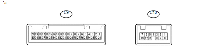
(a) Measure the voltage, resistance and check for pulses according to the value(s) in the table below.
|
Terminal No. (Symbol) |
Wiring Color |
Terminal Description |
Condition |
Specified Condition |
|---|---|---|---|---|
|
C9-1 (CANH) - Body ground |
G - Body ground |
CAN communication line |
- |
- |
|
C9-2 (CANL) - Body ground |
W - Body ground |
CAN communication line |
- |
- |
|
C9-4 (MSCH) - Body ground |
B - Body ground |
Local bus communication line |
- |
- |
|
C9- 5 (MSCL) - Body ground |
W - Body ground |
Local bus communication line |
- |
- |
|
C9-7 (EL) - Body ground |
V - Body ground |
LH turn indicator light signal (Input) |
Ignition switch ON, LH turn signal switch off |
11 to 14 V |
|
Ignition switch ON, LH turn signal switch on |
Below 1 V |
|||
|
C9-8 (ER) - Body ground |
GR - Body ground |
RH turn indicator light signal (Input) |
Ignition switch ON, RH turn signal switch off |
11 to 14 V |
|
Ignition switch ON, RH turn signal switch on |
Below 1 V |
|||
|
C9-9 (SW) - Body ground |
R - Body ground |
Turn switch signal |
Ignition switch ON, LH and RH turn signal switch off |
11 to 14 V |
|
Ignition switch ON, LH or RH turn signal switch on |
Below 1 V |
|||
|
C9-11 (BKSW) - Body ground |
L - Body ground |
Stop light switch signal |
Stop light switch on |
11 to 14 V |
|
Stop light switch off |
Below 1 V |
|||
|
C9-13 (HAZ) - Body ground |
Y - Body ground |
Hazard warning signal switch signal |
Ignition switch ON, hazard warning signal switch not pressed |
11 to 14 V |
|
Ignition switch ON, hazard warning signal switch pressed |
Below 1 V |
|||
|
C9-15 (ILL-) - Body ground |
BE - Body ground |
Illumination signal |
Headlight dimmer switch off |
Below 1 V |
|
Headlight dimmer switch in tail or head position |
Pulse generation |
|||
|
C9-17 (EP) - Body ground |
W-B - Body ground |
Ground |
Always |
Below 1 ╬® |
|
C9-18 (ES) - Body ground |
W-B - Body ground |
Ground |
Always |
Below 1 ╬® |
|
C9-19 (B) - Body ground |
P - Body ground |
Battery |
Always |
11 to 14 V |
|
C9-20 (IG+) - Body ground |
BE - Body ground |
Ignition switch signal |
Ignition switch off |
Below 1 V |
|
Ignition switch ON |
11 to 14 V |
|||
|
C9-21 (L) - C9-23 (E3) |
BE - G |
Fuel level signal |
Ignition switch ON, fuel level full |
Below 1 V |
|
Ignition switch ON, fuel level low (fuel level warning light on) |
4.5 to 9 V |
|||
|
C9-25 (S) - Body ground |
LG - Body ground |
Oil pressure signal |
Ignition switch ON, oil pressure warning OFF |
11 to 14 V |
|
Ignition switch ON, oil pressure warning ON |
Below 1 V |
|||
|
C9-26 (WLVL) - Body ground*1 |
B - Body ground |
Washer fluid level signal |
Ignition switch ON, washer fluid level not low |
11 to 14 V |
|
Ignition switch ON, washer fluid level low |
Below 1 V |
|||
|
C9-28 (SW) - Body ground*2 |
LG - Body ground |
Brake fluid level signal |
Ignition switch ON, brake fluid level not low |
11 to 14 V |
|
Ignition switch ON, brake fluid level low |
Below 1 V |
|||
|
C9-30 (MSM+) - Body ground |
P - Body ground |
Steering pad switch assembly signal |
Ignition switch ON, enter, top and back switches on steering pad switch assembly not pushed |
4.8 to 5.2 V |
|
Ignition switch ON, enter, top or back switches on steering pad switch assembly pushed |
Below 1 V |
|||
|
C9-32 (MSSL) - Body ground |
SB - Body ground |
Steering pad switch assembly signal |
Ignition switch ON, enter, top and back switches on steering pad switch assembly not pushed |
4.8 to 5.2 V |
|
Ignition switch ON, enter, top or back switches on steering pad switch assembly pushed |
Below 1 V |
|||
|
C9-34 (MSTI) - Body ground |
L - Body ground |
Steering pad switch assembly signal |
Ignition switch ON, up, down, right, and left switches on steering pad switch assembly not pushed |
4.8 to 5.2 V |
|
Ignition switch ON, up, down, right, or left switches on steering pad switch assembly pushed |
Below 1 V |
|||
|
C9-36 (OIL) - Body ground*3 |
W - Body ground |
Oil level switch signal |
Ignition switch ON, oil level low |
11 to 14 V |
|
Ignition switch ON, oil level not low |
Below 1 V |
|||
|
C9-37 (VCM) - Body ground*2*3 |
LG - Body ground |
Vacuum switch signal |
Ignition switch ON, vacuum pressure not low |
11 to 14 V |
|
Ignition switch ON, vacuum pressure low |
Below 1 V |
|||
|
C9-39 (SI) - Body ground |
G - Body ground |
Speed signal for other system (Input) |
Ignition switch ON, wheel being rotated |
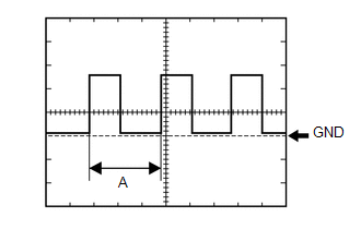
Pulse generation (See waveform 1) |
|
C9-40 (+S) - Body ground |
V - Body ground |
Speed signal for other system (Output) |
Ignition switch ON, wheel being rotated |
Pulse generation (See waveform 1) |
|
C10-1 (B) - Body ground |
V - Body ground |
Battery |
Always |
11 to 14 V |
|
C10-3 (RRT) - Body ground |
L - Body ground |
RH turn indicator light signal (Input) |
Ignition switch ON, RH turn signal switch off |
Below 1 V |
|
Ignition switch ON, RH turn signal switch on |
11 to 14 V ŌåÉŌåÆ Below 1 V |
|||
|
C10-5 (RLT) - Body ground |
Y - Body ground |
LH turn indicator light signal (Output) |
Ignition switch ON, LH turn indicator light off |
Below 1 V |
|
Ignition switch ON, LH turn indicator light blinking |
11 to 14 V ŌåÉŌåÆ Below 1 V |
|||
|
C10-9 (LL) - Body ground |
BE - Body ground |
LH turn indicator light signal (Output) |
Ignition switch ON, LH turn indicator light off |
Below 1 V |
|
Ignition switch ON, LH turn indicator light blinking |
11 to 14 V ŌåÉŌåÆ Below 1 V |
|||
|
C10-11 (TLT) - Body ground*4 |
V - Body ground |
LH turn indicator light signal (Output) |
Ignition switch ON, LH turn indicator light off |
Below 1 V |
|
Ignition switch ON, LH turn indicator light blinking |
11 to 14 V ŌåÉŌåÆ Below 1 V |
|||
|
C10-12 (TRT) - Body ground*4 |
SB - Body ground |
RH turn indicator light signal (Output) |
Ignition switch ON, RH turn signal switch off |
Below 1 V |
|
Ignition switch ON, RH turn signal switch on |
11 to 14 V ŌåÉŌåÆ Below 1 V |
|||
|
C10-13 (B) - Body ground |
W - Body ground |
Battery |
Always |
11 to 14 V |
|
C10-10 (LR) - Body ground |
SB - Body ground |
RH turn indicator light signal (Output) |
Ignition switch ON, RH turn indicator light off |
Below 1 V |
|
Ignition switch ON, RH turn indicator light blinking |
11 to 14 V ŌåÉŌåÆ Below 1 V |
- *1: Washer Fluid Level Warning
- *2: for Vacuum Booster Type
- *3: for 2GR-FKS
- *4: w/ Trailer Towing System
(1) Waveform 1 (Reference):
|
Item |
Condition |
|---|---|
|
Tool Setting |
5 V/DIV., 20 ms./DIV. |
|
Vehicle Condition |
Ignition switch ON, wheel being rotated |
HINT:
When the system is functioning normally, one wheel revolution generates 4 pulses. As the vehicle speed increases, the width indicated by (A) in the illustration narrows.
 Problem Symptoms Table
PROBLEM SYMPTOMS TABLE
HINT:
Use the table below to help determine the cause of problem symptoms.
If multiple suspected areas are listed, the potential causes of the symptom
are list ...
 Data List / Active Test
DATA LIST / ACTIVE TEST
1. DATA LIST
HINT:
Using the Techstream to read the Data List allows the values or states of switches,
sensors, actuators and other items to be read without removing any p ...
Other materials:
Dtc Check / Clear
DTC CHECK / CLEAR
1. CHECK FOR DTC
HINT:
When using the Techstream with the engine switch off, connect the Techstream
to the DLC3 and turn a courtesy light switch on and off at intervals of 1.5 seconds
or less until communication between the Techstream and the vehicle begins. Then
select th ...
Disposal
DISPOSAL
CAUTION / NOTICE / HINT
CAUTION:
Before performing pre-disposal deployment of any SRS part, review and closely
follow all applicable environmental and hazardous material regulations. Predisposal
deployment may be considered hazardous material treatment.
PROCEDURE
1. PRECAUTION
...
Diameter of the Tire is not Uniform (C1337)
DESCRIPTION
The skid control ECU (master cylinder solenoid) measures the speed of each wheel
by receiving signals from the speed sensors. These signals are used for recognizing
whether all 4 wheels are operating properly. Therefore, all wheel signals must be
equal.
DTC No.
...
