Toyota Tacoma (2015-2018) Service Manual: Terminals Of Ecu
TERMINALS OF ECU
1. CHECK DRIVER SIDE JUNCTION BLOCK AND MAIN BODY ECU (MULTIPLEX NETWORK BODY ECU)
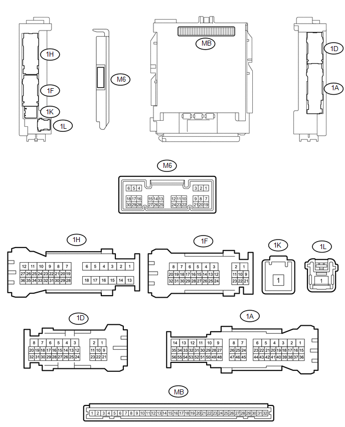
(a) Disconnect the MB main body ECU (multiplex network body ECU) connectors.
(b) Measure the voltage and resistance according to the value(s) in the table below.
HINT:
Measure the values on the wire harness side with the connectors disconnected.
|
Tester Connection |
Wiring Color |
Terminal Description |
Condition |
Specified Condition |
|---|---|---|---|---|
|
MB-11(GND1) - Body ground |
- |
Ground |
Always |
Below 1 Ω |
|
MB-31 (BECU) - Body ground |
- |
Battery power supply |
Always |
11 to 14 V |
|
MB-30 (ACC) - Body ground |
- |
ACC power supply |
Ignition switch ACC |
11 to 14 V |
|
MB-30 (ACC) - Body ground |
- |
ACC power supply |
Ignition switch off |
Below 1 V |
|
MB-32 (IG) - Body ground |
- |
IG power supply |
Ignition switch ON |
11 to 14 V |
|
MB-32 (IG) - Body ground |
- |
IG power supply |
Ignition switch off |
Below 1 V |
If the result is not as specified, there may be a malfunction in the wire harness.
(c) Reconnect the MB main body ECU (multiplex network body ECU) connectors.
(d) Measure the voltage and check for pulses according to the value(s) in the table below.
|
Tester Connection |
Wiring Color |
Terminal Description |
Condition |
Specified Condition |
|---|---|---|---|---|
|
1D-1 (ACT+) - Body ground |
R - Body ground |
Door lock motor unlock drive output (except driver door) |
Door control switch (power window regulator master switch assembly) or driver door key cylinder off |
Below 1 V |
|
Door control switch (power window regulator master switch assembly) or driver door key cylinder unlocked |
11 to 14 V |
|||
|
1H-12 (ACT+) - Body ground |
LA-R - Body ground |
Door lock motor unlock drive output (except driver door) |
Door control switch (power window regulator master switch assembly) or driver door key cylinder off |
Below 1 V |
|
Door control switch (power window regulator master switch assembly) or driver door key cylinder unlocked |
11 to 14 V |
|||
|
1H-10 (ACT-) - Body ground |
LA-G - Body ground |
Door lock motor lock drive output (all doors) |
Door control switch (power window regulator master switch assembly) or driver door key cylinder off |
Below 1 V |
|
Door control switch (power window regulator master switch assembly) or driver door key cylinder locked |
11 to 14 V |
|||
|
1D-3 (ACT-) - Body ground |
G - Body ground |
Door lock motor lock drive output (all doors) |
Door control switch (power window regulator master switch assembly) or driver door key cylinder off |
Below 1 V |
|
Door control switch (power window regulator master switch assembly) or driver door key cylinder locked |
11 to 14 V |
|||
|
1D-2 (ACTD) - Body ground |
B - Body ground |
Driver door lock motor unlock drive output |
Door control switch (power window regulator master switch assembly) or driver door key cylinder off |
Below 1 V |
|
Door control switch (power window regulator master switch assembly) or driver door key cylinder unlocked |
11 to 14 V |
|||
|
M6-27 (FRCY) - Body ground |
LG - Body ground |
Front door courtesy light switch RH input |
Front door RH open |
Below 1 V |
|
M6-27 (FRCY) - Body ground |
LG - Body ground |
Front door courtesy light switch RH input |
Front door RH open |
11 to 14 V |
|
M6-6 (FLCY) - Body ground |
Y - Body ground |
Front door courtesy light switch LH input |
Front door LH open |
Below 1 V |
|
M6-6 (FLCY) - Body ground |
Y - Body ground |
Front door courtesy light switch LH input |
Front door LH closed |
11 to 14 V |
|
1H-36 (LCTY) - Body ground |
P - Body ground |
Rear door courtesy light switch LH input*1 Upper access panel lock assembly LH input*2 Lower access panel lock assembly LH input*2 |
Rear door LH open |
Below 1 V |
|
1H-36 (LCTY) - Body ground |
P - Body ground |
Rear door courtesy light switch LH input*1 Upper access panel lock assembly LH input*2 Lower access panel lock assembly LH input*2 |
Rear door LH closed |
Pulse generation |
|
1D-30 (RCTY) - Body ground |
V - Body ground |
Rear door courtesy light switch RH input*1 Upper access panel lock assembly RH input*2 Lower access panel lock assembly RH input*2 |
Rear door RH open |
Below 1 V |
|
1D-30 (RCTY) - Body ground |
V - Body ground |
Rear door courtesy light switch RH input*1 Upper access panel lock assembly RH input*2 Lower access panel lock assembly RH input*2 |
Rear door RH closed |
Pulse generation |
|
1D-11 (LSFL) - Body ground |
P - Body ground |
Front door LH unlock detection switch input |
Front door LH unlocked |
Below 1 V |
|
1D-11 (LSFL) - Body ground |
P - Body ground |
Front door LH unlock detection switch input |
Ignition switch off, all doors closed and front door LH locked |
Pulse generation |
|
1D-24 (LSFR) - Body ground |
GR - Body ground |
Front door RH unlock detection switch input |
Front door RH unlocked |
Below 1 V |
|
1D-24 (LSFR) - Body ground |
GR - Body ground |
Front door RH unlock detection switch input |
Ignition switch off, all doors closed and front door RH locked |
Pulse generation |
|
1A-41 (LSR) - Body ground |
Y - Body ground |
Rear door RH unlock detection switch input |
Rear door RH or LH unlocked |
Below 1 V |
|
1A-41 (LSR) - Body ground |
Y - Body ground |
Rear door RH unlock detection switch input |
Ignition switch off, all doors closed and rear door RH and LH locked |
Pulse generation |
|
1H-27 (LSR) - Body ground |
L - Body ground |
Rear door LH unlock detection switch input |
Rear door LH or RH unlocked |
Below 1 V |
|
1H-27 (LSR) - Body ground |
L - Body ground |
Rear door LH unlock detection switch input |
Ignition switch off, all doors closed and rear door LH and RH locked |
Pulse generation |
|
1F-29 (BZR) - Body ground |
Y - Body ground |
Wireless door lock buzzer signal |
Wireless door lock buzzer off |
Below 1 V |
|
1F-29 (BZR) - Body ground |
Y - Body ground |
Wireless door lock buzzer signal |
Wireless door lock buzzer on |
Pulse generation |
|
31-1D (KSW) - Body ground |
G - Body ground |
Key unlock warning switch input |
Key in ignition key cylinder |
Below 1 V |
|
No key in ignition key cylinder |
11 to 14 V or Pulse generation |
- *1: for Double Cab
- *2: for Access Cab
If the result is not as specified, there may be a malfunction in the wire harness.
2. CHECK DOOR CONTROL RECEIVER (w/ Tire Pressure Warning System)

(a) Disconnect the T25 door control receiver connector.
(b) Measure the resistance and voltage according to the value(s) in the table below.
HINT:
Measure the values on the wire harness side with the connectors disconnected.
|
Terminal No. (Symbol) |
Wiring Color |
Terminal Description |
Condition |
Specified Condition |
|---|---|---|---|---|
|
T25-7 (+B) - Body ground |
BE - Body ground |
Battery (power supply) |
Always |
11 to 14 V |
|
T25-12 (GND) - Body ground |
W-B - Body ground |
Ground |
Always |
Below 1 Ω |
- If the result is not as specified, there may be a malfunction in the wire harness.
(c) Reconnect the T25 door control receiver connector.
(d) Measure the voltage according to the value(s) in the table below.
|
Terminal No. (Symbol) |
Wiring Color |
Terminal Description |
Condition |
Specified Condition |
|---|---|---|---|---|
|
T25-5 (PRG) - T25-12 (GND) |
GR - W-B |
Signal input from main body ECU (multiplex network body ECU) |
Key inserted in ignition key cylinder → Key pulled out of ignition key cylinder |
11 to 14 V → Pulse generation → 11 to 14 V |
|
T25-4 (RDA) - T25-12 (GND) |
B - W-B |
Signal output to main body ECU (multiplex network body ECU) |
Ignition switch off, all doors closed and door control transmitter module set sub-assembly switch not pressed |
11 to 14 V |
|
Ignition switch off, all doors closed and door control transmitter module set sub-assembly switch pressed |
Pulse generation |
- If the result is not as specified, the door control receiver may have a malfunction.
3. CHECK DOOR CONTROL RECEIVER (w/o Tire Pressure Warning System)

(a) Disconnect the D7 door control receiver connector.
(b) Measure the resistance according to the value(s) in the table below.
HINT:
Measure the values on the wire harness side with the connectors disconnected.
|
Terminal No. (Symbol) |
Wiring Color |
Terminal Description |
Condition |
Specified Condition |
|---|---|---|---|---|
|
D7-5 (+B) - Body ground |
V - Body ground |
Battery (power supply) |
Always |
11 to 14 V |
|
D7-1 (GND) - Body ground |
W-B - Body ground |
Ground |
Always |
Below 1 Ω |
- If the result is not as specified, there may be a malfunction in the wire harness.
(c) Reconnect the D7 door control receiver connector.
(d) Measure the voltage according to the value(s) in the table below.
|
Terminal No. (Symbol) |
Wiring Color |
Terminal Description |
Condition |
Specified Condition |
|---|---|---|---|---|
|
D7-3 (PRG) - D7-1 (GND) |
GR - W-B |
Signal input from main body ECU (multiplex network body ECU) |
Key inserted in ignition key cylinder → Key pulled out of ignition key cylinder |
11 to 14 V → Pulse generation → 11 to 14 V |
|
D7-2 (RDA) - D7-1 (GND) |
B - W-B |
Signal output to main body ECU (multiplex network body ECU) |
Ignition switch off, all doors closed and door control transmitter module set sub-assembly switch not pressed |
11 to 14 V |
|
Ignition switch off, all doors closed and door control transmitter module set sub-assembly switch pressed |
Pulse generation |
- If the result is not as specified, the door control receiver may have a malfunction.
 Diagnosis System
DIAGNOSIS SYSTEM
1. CHECK DLC3
(a) Check the DLC3 (See page ).
2. INSPECT BATTERY VOLTAGE
(a) Measure the battery voltage.
Standard Voltage:
11 to 14 V
If the voltage is below 11 V, recharge ...
 Data List / Active Test
DATA LIST / ACTIVE TEST
1. DATA LIST
HINT:
Using the Techstream to read the Data List allows the values or states of switches,
sensors, actuators and other items to be read without removing any p ...
Other materials:
Communication Error from VSC to ECM Invalid Serial Data Received (P163081)
DESCRIPTION
The skid control ECU (master cylinder solenoid)*1 or skid control ECU (brake
actuator assembly)*2 sends signals such as cruise control cancel signals and brake
demand response signals to the ECM when the dynamic radar cruise control system
is operating.
DTC No.
...
Master Cylinder Pressure Sensor Zero Point High Malfunction (C1422)
DESCRIPTION
DTC No.
Detection Item
DTC Detection Condition
Trouble Area
C1422
Master Cylinder Pressure Sensor Zero Point High Malfunction
When vehicle speed is 3 km/h (2 mph) or more and stop light switch assembly
...
System Voltage Circuit Short to Ground or Open (P056014)
DESCRIPTION
The battery supplies power to the ECM even when the ignition switch is off. This
power allows the ECM to store data such as DTC history, freeze frame data and fuel
trim values. If the battery voltage falls below a minimum level, the ECM data is
cleared and the ECM determines that ...
