Toyota Tacoma (2015-2018) Service Manual: Terminals Of Ecu
TERMINALS OF ECU
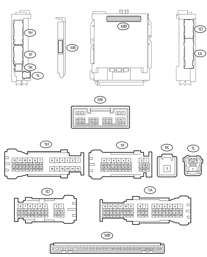
1. CHECK MAIN BODY ECU (MULTIPLEX NETWORK BODY ECU) AND DRIVER SIDE JUNCTION BLOCK
(a) Remove the main body ECU (multiplex network body ECU) from the driver side
junction block (See page .gif) ).
).
(b) Disconnect the 1D driver side junction block connector.
(c) Measure the voltage and resistance according to the value(s) in the table below.
|
Terminal No. (Symbol) |
Wiring Color |
Terminal Description |
Condition |
Specified Condition |
|---|---|---|---|---|
|
MB-11 (GND1) - Body ground |
None - Body ground |
Ground |
Always |
Below 1 Ω |
|
MB-31 (BECU) - Body ground |
None - Body ground |
Battery power supply |
Always |
11 to 14 V |
|
MB-30 (ACC) - Body ground |
None - Body ground |
ACC power supply |
Ignition switch ON(ACC) |
11 to 14 V |
|
MB-32 (IG) - Body ground |
None - Body ground |
Ignition switch power supply |
Ignition switch ON(IG) |
11 to 14 V |
|
1D-31 (KSW) - Body ground |
G - Body ground |
Unlock warning switch input |
No Key in ignition key cylinder (off) |
10 kΩ or higher |
|
Key inserted ignition key cylinder (on) |
Below 1 Ω |
(d) Install the main body ECU (multiplex network body ECU) to the driver side
junction block (See page ).
(e) Reconnect the 1D driver side junction block connector.
(f) Measure the voltage and check for pulse according to the value(s) in the table below.
|
Terminal No. (Symbol) |
Wiring Color |
Terminal Description |
Condition |
Specified Condition |
|---|---|---|---|---|
|
M6-6 (FLCY) - Body ground |
Y - Body ground |
Front door LH courtesy light switch input |
Front door LH open |
Below 1 V |
|
Front door LH closed |
Pulse generation |
|||
|
1D-31 (KSW) - Body ground |
G - Body ground |
Unlock warning switch input |
No Key in ignition key cylinder (off) |
11 to 14 V |
|
Key inserted ignition key cylinder (on) |
Below 1 V |
 Diagnosis System
DIAGNOSIS SYSTEM
1. CHECK DLC3
(a) Check the DLC3 (See page ).
2. INSPECT BATTERY VOLTAGE
(a) Measure the battery voltage.
Standard voltage:
11 to 14 V
If the voltage is below 11 V, replace t ...
 Key Reminder Buzzer does not Sound
DESCRIPTION
The key reminder warning buzzer sounds when the driver side door is opened while
the ignition switch is in the LOCK or ACC positions. The key reminder warning buzzer
is activated when ...
Other materials:
Meter Illumination is Always Dark
DESCRIPTION
In this circuit, the combination meter assembly receives auto dimmer signals
from the main body ECU (multiplex network body ECU) using the CAN communication
system (CAN V1 Bus). When the meter CPU receives an auto dimmer signal, it dims
the meter illumination (warning and indicato ...
Components
COMPONENTS
ILLUSTRATION
*A
for Access Cab
-
-
*1
NO. 1 FRONT DOOR NAME PLATE
*2
NO. 1 ROOF SIDE NAME PLATE
â—Ź
Non-reusable part
-
-
ILLUSTRAT ...
ABS Warning Light does not Come ON
DESCRIPTION
Refer to ABS Warning Light Remains ON (See page
).
WIRING DIAGRAM
Refer to ABS Warning Light Remains ON (See page
).
CAUTION / NOTICE / HINT
NOTICE:
When replacing the skid control ECU (master cylinder solenoid), perform
calibration (See page
).
Inspect the ...
