Toyota Tacoma (2015-2018) Service Manual: Terminals Of Ecu
TERMINALS OF ECU
CHECK ECM
HINT:
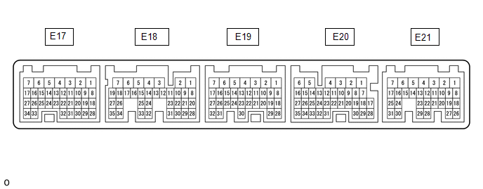
The standard voltage, resistance and waveform between each pair of the ECM terminals is shown in the table below. The appropriate conditions for checking each pair of the terminals is also indicated. The result of checks should be compared with the standard voltage, resistance and waveform for each pair of the terminals as displayed in the Specified Condition column. The illustration above can be used as a reference to identify the ECM terminal locations.
|
Terminal No. (Symbols) |
Wiring Color |
Terminal Description |
Condition |
Specified Condition |
|---|---|---|---|---|
|
E17-3 (E1) - Body ground |
W-B - Body ground |
Ground |
Always |
Below 1 V |
|
E19-17 (SFTU) - E17-3 (E1) |
SB - W-B |
Up-shift position switch signal |
Ignition switch ON and shift lever in S |
11 to 14 V |
|
Ignition switch ON and shift lever in "+" (Up-shift) |
Below 1 V |
|||
|
E19-27 (SFTD) - E17-3 (E1) |
R - W-B |
Down-shift position switch signal |
Ignition switch ON and shift lever in S |
11 to 14 V |
|
Ignition switch ON and shift lever in "-" (Down-shift) |
Below 1 V |
|||
|
E19-30 (S) - E17-3 (E1) |
B - W-B |
S shift position switch signal |
Ignition switch ON and shift lever in S, "+" or "-" |
11 to 14 V |
|
Ignition switch ON and shift lever not in S, "+" or "-" |
Below 1 V |
|||
|
E20-18 (D) - E17-3 (E1) |
SB - W-B |
D shift position signal |
Ignition switch ON, shift lever in D |
11 to 14 V |
|
Ignition switch ON, shift lever not in D |
Below 1 V |
|||
|
E20-22 (CCS) - E17-3 (E1) |
B - W-B |
Cruise control main switch output signal |
CANCEL switch ON |
1509 to 1571 Ω |
|
-SET switch ON |
617 to 643 Ω |
|||
|
+RES switch ON |
235 to 245 Ω |
|||
|
Cruise control main switch (ON-OFF button) not pushed |
1 MΩ or higher |
|||
|
Cruise control main switch (ON-OFF button) pushed |
Below 2.5 Ω |
|||
|
E21-10 (STP) - E17-3 (E1) |
P - W-B |
Stop light switch input signal |
Brake pedal depressed |
11 to 14 V |
|
Brake pedal released |
Below 1 V |
|||
|
E21-11 (ST1-) - E17-3 (E1) |
V - W-B |
Stop light switch assembly signal |
Ignition switch ON, brake pedal depressed |
Below 1 V |
|
Ignition switch ON, brake pedal released |
11 to 14 V |
|||
|
E21-19 (TC) - E17-3 (E1) |
G - W-B |
DTC output signal |
Ignition switch ON |
11 to 14 V |
|
Ignition switch ON, connect terminals TC and CG of DLC3 |
Below 2 V |
.png)
NOTICE:
Do not apply excessive force to the connector. If a force of 10 kg or more is applied, the connector may be broken.
CHECK FORWARD RECOGNITION CAMERA
|
Terminal No. (Symbol) |
Wiring Color |
Terminal Description |
Condition |
Specified Condition |
|---|---|---|---|---|
|
F46-8 (BZ) - F46-10 (GND) |
L - W-B |
Skid control buzzer output |
Ignition switch to ON, buzzer not sounding |
11 to 14 V |
|
Ignition switch to ON, buzzer sounding |
Below 1 V |
|||
|
F46-7 (IGB) - F46-10 (GND) |
BE - W-B |
Power source |
Ignition switch to ON |
11 to 14 V |
|
Ignition switch off |
Below 1 V |
|||
|
F46-5 (CA1P) - F46-10 (GND) |
L - W-B |
CAN communication signal |
Ignition switch to ON |
Pulse generation (See waveform 1) |
|
F46-11 (CA1N) - F46-10 (GND) |
W - W-B |
CAN communication signal |
Ignition switch to ON |
Pulse generation (See waveform 2) |
|
F46-6 (CANH) - F46-10 (GND) |
B - W-B |
CAN communication signal |
Ignition switch to ON |
Pulse generation (See waveform 1) |
|
F46-12 (CANL) - F46-10 (GND) |
W - W-B |
CAN communication signal |
Ignition switch to ON |
Pulse generation (See waveform 2) |
|
F46-3 (LKSW) - F46-10 (GND) |
GR - W-B |
Steering pad switch assembly signal (distance control signal) |
Ignition switch to ON, steering pad switch assembly (distance control switch) off |
4.75 to 5.25 V |
|
Ignition switch to ON, steering pad switch assembly (distance control switch) on |
Below 1 V |
|||
|
F46-10 (GND) - Body ground |
W-B - Body ground |
Ground |
Always |
Below 1 Ω |
.png)
(a) Waveform 1
(1) CAN communication signal
|
Item |
Content |
|---|---|
|
Tester Connection |
|
|
Tool Setting |
1 V/DIV., 10 ÎĽsec./DIV. |
|
Condition |
Ignition switch to ON |
HINT:
The waveform varies depending on the CAN communication signal.
(b) Waveform 2
.png)
(1) CAN communication signal
|
Item |
Content |
|---|---|
|
Tester Connection |
|
|
Tool Setting |
1 V/DIV., 10 ÎĽsec./DIV. |
|
Condition |
Ignition switch to ON |
HINT:
The waveform varies depending on the CAN communication signal.
.png)
|
Terminal No. (Symbol) |
Wiring Color |
Terminal Description |
Condition |
Specified Condition |
|---|---|---|---|---|
|
M8-1 (SGND) - Body ground |
W-B - Body ground |
Ground |
Always |
Below 1 Ω |
|
M8-2 (CA2L) - M8-1 (SGND) |
W - W-B |
CAN communication signal |
Ignition switch to ON |
Pulse generation (See waveform 2) |
|
M8-3 (CA2H) - M8-1 (SGND) |
W-B - W-B |
CAN communication signal |
Ignition switch to ON |
Pulse generation (See waveform 1) |
|
M8-5 (CA1P) - M8-1 (SGND) |
B - W-B |
CAN communication signal |
Ignition switch to ON |
Pulse generation (See waveform 1) |
|
M8-6 (CA1N) - M8-1 (SGND) |
W - W-B |
CAN communication signal |
Ignition switch to ON |
Pulse generation (See waveform 2) |
|
M8-8 (IGB) - M8-1 (SGND) |
LG - W-B |
Power source |
Ignition switch to ON |
11 to 14 V |
CHECK MILLIMETER WAVE RADAR SENSOR
(a) Waveform 1
(1) CAN communication signal
|
Item |
Content |
|---|---|
|
Tester Connection |
|
|
Tool Setting |
1 V/DIV., 10 ÎĽsec./DIV. |
|
Condition |
Ignition switch to ON |
HINT:
The waveform varies depending on the CAN communication signal.
(b) Waveform 2
(1) CAN communication signal
|
Item |
Content |
|---|---|
|
Tester Connection |
|
|
Tool Setting |
1 V/DIV., 10 ÎĽsec./DIV. |
|
Condition |
Ignition switch to ON |
HINT:
The waveform varies depending on the CAN communication signal.
 Problem Symptoms Table
PROBLEM SYMPTOMS TABLE
NOTICE:
Before replacing the ECM, refer to Registration.
w/ Smart Key System: Click here
w/o Smart Key System: Click here
When the millimeter wave rad ...
 Diagnosis System
DIAGNOSIS SYSTEM
DIAGNOSIS FUNCTION
(a) The diagnosis function turns off the cruise control indicator, illuminates
the master warning light and displays a warning message when a malfunction is det ...
Other materials:
Tires
Replace or rotate tires in accordance with maintenance schedules and treadwear.
■ Checking tire
1. New tread
2. Treadwear indicator
3. Worn tread
The location of treadwear indicators is shown by the “TWI” or “
” marks, etc., molded on the sidewall of each tire.
Check spare ti ...
Brake Switch "A" Circuit (P0571)
DESCRIPTION
Detection condition 1:
When the brake pedal is depressed, the stop light switch assembly outputs
a signal to the ECM. When the ECM receives the signal, it cancels control
of vehicle speed by the dynamic radar cruise control system. The fail-safe
function operates to ...
On-vehicle Inspection
ON-VEHICLE INSPECTION
CAUTION / NOTICE / HINT
CAUTION:
Be sure to correctly follow the removal and installation procedures for the front
airbag sensors.
PROCEDURE
1. INSPECT FRONT AIRBAG SENSOR (for Vehicle not Involved in Collision)
(a) Perform a diagnostic system check (See page
).
2. I ...
