Toyota Tacoma (2015-2018) Service Manual: Terminals Of Ecu
TERMINALS OF ECU
CHECK ECM
HINT:
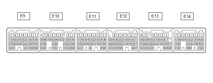
The standard voltage, resistance and waveform between each pair of the ECM terminals is shown in the table below. The appropriate conditions for checking each pair of the terminals is also indicated. The result of checks should be compared with the standard voltage, resistance and waveform for each pair of the terminals as displayed in the Specified Condition column. The illustration above can be used as a reference to identify the ECM terminal locations.
|
Terminal No. (Symbols) |
Wiring Color |
Terminal Description |
Condition |
Specified Condition |
|---|---|---|---|---|
|
E10-23 (VC) - E11-1 (E1)*2 |
LG - W-B |
Neutral position switch power supply |
Ignition switch ON |
4.5 to 5.5 V |
|
E11-1 (E1) - Body ground |
W-B - Body ground |
Ground |
Always |
Below 1 V |
|
E11-22 (NPSW) - E9-23 (ETHW)*2 |
L - BR |
Neutral position switch signal |
Ignition switch ON, shift lever in neutral |
2.7 to 4.3 V |
|
Ignition switch ON, shift lever in any other than neutral |
0.7 to 1.9 V |
|||
|
E12-6 (+BM) - E11-1 (E1) |
GR - W-B |
Power source of throttle actuator |
Always |
11 to 14 V |
|
E12-27 (D) - E11-1 (E1)*1 |
R - W-B |
D shift position signal |
Ignition switch ON, shift lever in D |
11 to 14 V |
|
Ignition switch ON, shift lever not in D |
Below 1 V |
|||
|
E12-27 (D) - E11-1 (E1)*2 |
R - W-B |
Clutch switch input signal |
Ignition switch ON, clutch pedal depressed |
Below 1 V |
|
Ignition switch ON, clutch pedal released |
11 to 14 V |
|||
|
E13-7 (SFTD) - E11-1 (E1)*1 |
R - W-B |
Down-shift position switch signal |
Ignition switch ON and shift lever in S |
11 to 14 V |
|
Ignition switch ON and shift lever in "-" (Down-shift) |
Below 1 V |
|||
|
E13-8 (SFTU) - E11-1 (E1)*1 |
G - W-B |
Up-shift position switch signal |
Ignition switch ON and shift lever in S |
11 to 14 V |
|
Ignition switch ON and shift lever in "+" (Up-shift) |
Below 1 V |
|||
|
E13-15 (ST1-) - E11-1 (E1) |
V - W-B |
Stop light switch assembly signal |
Ignition switch ON, brake pedal depressed |
Below 1 V |
|
Ignition switch ON, brake pedal released |
11 to 14 V |
|||
|
E13-16 (STP) - E11-1 (E1) |
P - W-B |
Stop light switch input signal |
Brake pedal depressed |
11 to 14 V |
|
Brake pedal released |
Below 1 V |
|||
|
E13-17 (CCS) - E11-1 (E1) |
B - W-B |
Cruise control main switch output signal |
CANCEL switch ON |
1509 to 1571 Ω |
|
-SET switch ON |
617 to 643 Ω |
|||
|
+RES switch ON |
235 to 245 Ω |
|||
|
Cruise control main switch (ON-OFF button) not pushed |
1 MΩ or higher |
|||
|
Cruise control main switch (ON-OFF button) pushed |
Below 2.5 Ω |
|||
|
E13-32 (S) - E11-1 (E1)*1 |
P - W-B |
S shift position switch signal |
Ignition switch ON and shift lever in S, "+" or "-" |
11 to 14 V |
|
Ignition switch ON and shift lever not in S, "+" or "-" |
Below 1 V |
|||
|
E14-2 (BATT) - E11-1 (E1) |
L - W-B |
Battery (for measuring battery voltage and for ECM memory) |
Always |
11 to 14 V |
|
E14-20 (TC) - E11-1 (E1) |
G - W-B |
DTC output signal |
Ignition switch ON |
11 to 14 V |
|
Ignition switch ON, connect terminals TC and CG of DLC3 |
Below 2 V |
- *1: for Automatic Transmission
- *2: for Manual Transmission

NOTICE:
Do not apply excessive force to the connector. If a force of 10 kg or more is applied, the connector may be broken.
CHECK FORWARD RECOGNITION CAMERA
|
Terminal No. (Symbol) |
Wiring Color |
Terminal Description |
Condition |
Specified Condition |
|---|---|---|---|---|
|
F46-8 (BZ) - F46-10 (GND) |
L - W-B |
Skid control buzzer output |
Ignition switch to ON, buzzer not sounding |
11 to 14 V |
|
Ignition switch to ON, buzzer sounding |
Below 1 V |
|||
|
F46-7 (IGB) - F46-10 (GND) |
BE - W-B |
Power source |
Ignition switch to ON |
11 to 14 V |
|
Ignition switch off |
Below 1 V |
|||
|
F46-5 (CA1P) - F46-10 (GND) |
L - W-B |
CAN communication signal |
Ignition switch to ON |
Pulse generation (See waveform 1) |
|
F46-11 (CA1N) - F46-10 (GND) |
W - W-B |
CAN communication signal |
Ignition switch to ON |
Pulse generation (See waveform 2) |
|
F46-6 (CANH) - F46-10 (GND) |
B - W-B |
CAN communication signal |
Ignition switch to ON |
Pulse generation (See waveform 1) |
|
F46-12 (CANL) - F46-10 (GND) |
W - W-B |
CAN communication signal |
Ignition switch to ON |
Pulse generation (See waveform 2) |
|
F46-3 (LKSW) - F46-10 (GND) |
GR - W-B |
Steering pad switch assembly signal (distance control signal) |
Ignition switch to ON, steering pad switch assembly (distance control switch) off |
4.75 to 5.25 V |
|
Ignition switch to ON, steering pad switch assembly (distance control switch) on |
Below 1 V |
|||
|
F46-10 (GND) - Body ground |
W-B - Body ground |
Ground |
Always |
Below 1 Ω |
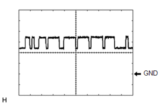
(a) Waveform 1
(1) CAN communication signal
|
Item |
Content |
|---|---|
|
Tester Connection |
|
|
Tool Setting |
1 V/DIV., 10 ÎĽsec./DIV. |
|
Condition |
Ignition switch to ON |
HINT:
The waveform varies depending on the CAN communication signal.
(b) Waveform 2
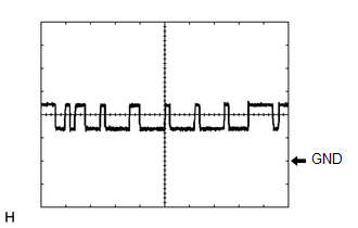
(1) CAN communication signal
|
Item |
Content |
|---|---|
|
Tester Connection |
|
|
Tool Setting |
1 V/DIV., 10 ÎĽsec./DIV. |
|
Condition |
Ignition switch to ON |
HINT:
The waveform varies depending on the CAN communication signal.

|
Terminal No. (Symbol) |
Wiring Color |
Terminal Description |
Condition |
Specified Condition |
|---|---|---|---|---|
|
M8-1 (SGND) - Body ground |
W-B - Body ground |
Ground |
Always |
Below 1 Ω |
|
M8-2 (CA2L) - M8-1 (SGND) |
W - W-B |
CAN communication signal |
Ignition switch to ON |
Pulse generation (See waveform 2) |
|
M8-3 (CA2H) - M8-1 (SGND) |
W-B - W-B |
CAN communication signal |
Ignition switch to ON |
Pulse generation (See waveform 1) |
|
M8-5 (CA1P) - M8-1 (SGND) |
B - W-B |
CAN communication signal |
Ignition switch to ON |
Pulse generation (See waveform 1) |
|
M8-6 (CA1N) - M8-1 (SGND) |
W - W-B |
CAN communication signal |
Ignition switch to ON |
Pulse generation (See waveform 2) |
|
M8-8 (IGB) - M8-1 (SGND) |
LG - W-B |
Power source |
Ignition switch to ON |
11 to 14 V |
CHECK MILLIMETER WAVE RADAR SENSOR
(a) Waveform 1
(1) CAN communication signal
|
Item |
Content |
|---|---|
|
Tester Connection |
|
|
Tool Setting |
1 V/DIV., 10 ÎĽsec./DIV. |
|
Condition |
Ignition switch to ON |
HINT:
The waveform varies depending on the CAN communication signal.
(b) Waveform 2
(1) CAN communication signal
|
Item |
Content |
|---|---|
|
Tester Connection |
|
|
Tool Setting |
1 V/DIV., 10 ÎĽsec./DIV. |
|
Condition |
Ignition switch to ON |
HINT:
The waveform varies depending on the CAN communication signal.
 Problem Symptoms Table
PROBLEM SYMPTOMS TABLE
NOTICE:
Before replacing the ECM, refer to Registration.
w/o Smart Key System: Click here
w/ Smart Key System: Click here
When the millimeter wave rad ...
 Dtc Check / Clear
DTC CHECK / CLEAR
NOTICE:
When the diagnosis system is changed from normal mode to check mode or vice versa,
all DTCs and freeze frame data recorded in normal mode are cleared. Before changing
m ...
Other materials:
Adjustment
ADJUSTMENT
PROCEDURE
1. REMOVE FRONT CONSOLE BOX
(See page )
2. ADJUST TRANSMISSION CONTROL CABLE ASSEMBLY
(a) Move the shift lever to N.
(b) Disconnect the end of the transmission control cable assembly from the transmission
floor shift assembly.
Text in Illustration
...
Driver Side Door ECU Communication Stop (B2321)
DESCRIPTION
This DTC is stored when LIN communication between the front power window regulator
motor assembly LH and main body ECU (multiplex network body ECU) stops for 10 seconds
or more.
DTC No.
DTC Detection Condition
Trouble Area
B2321
...
Theft Deterrent System cannot be Set or Unset
DESCRIPTION
When the ignition switch is turned off and all doors and the engine hood are
closed, the theft deterrent system is set when doors are locked by wireless operation*1,
key linked operation or entry operation*2. If all doors are closed but engine hood
is open when doors are locked by ...
