Toyota Tacoma (2015-2018) Service Manual: Adjustment
ADJUSTMENT
PROCEDURE
1. REMOVE FRONT CONSOLE BOX
(See page .gif) )
)
2. ADJUST TRANSMISSION CONTROL CABLE ASSEMBLY
(a) Move the shift lever to N.
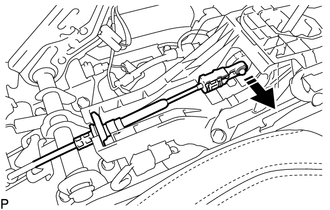
(b) Disconnect the end of the transmission control cable assembly from the transmission floor shift assembly.
 Text in Illustration
.png) |
Disconnect in this Direction |
|
(c) Push the 2 claws together at the top of the transmission control cable lock piece. While holding the 2 claws together, push the 2 lugs on the bottom of the lock piece toward each other and upward to pull out the lock piece. Text in Illustration
|
|
.png)
(d) Connect the end of the transmission control cable assembly to the transmission floor shift assembly.
.png) Text in Illustration
Text in Illustration
|
*1 |
Lock Piece |
|
|
Connect in this Direction |
NOTICE:
- Check that the park/neutral position switch and shift lever are in N.
- Make sure that the lock piece is pulled up.
- Push on the end of the cable all the way to the base of the transmission floor shift assembly pin.
|
(e) Push the lock piece into the adjuster case. Text in Illustration
NOTICE: Securely push in the lock piece until it locks. |
|
.png)
(f) After adjusting the shift lever position, check the operation and function of the shift lever. If there is a problem, adjust the position again.
3. INSTALL FRONT CONSOLE BOX
(See page )
 Components
COMPONENTS
ILLUSTRATION
...
 Installation
INSTALLATION
PROCEDURE
1. INSTALL TRANSMISSION CONTROL CABLE ASSEMBLY
(a) Install the transmission control cable assembly from outside the vehicle
body and attach the 3 claws of the cable retaine ...
Other materials:
Light bulbs
You may replace the following bulbs yourself. The difficulty level of replacement
varies depending on the bulb. If necessary bulb replacement seems difficult to perform,
contact your Toyota dealer.
For more information about replacing other light bulbs, contact your Toyota dealer.
■ Prep ...
Inspection
INSPECTION
PROCEDURE
1. INSPECT INPUT SHAFT
(a) Using a dial indicator and 2 V-blocks, measure the shaft runout.
Maximum runout:
0.03 mm (0.0012 in.)
If the runout is more than the maximum, replace the input shaft.
HINT:
Measure the 3 areas shown in the illustration wit ...
Precaution
PRECAUTION
1. HANDLING PRECAUTIONS FOR STEERING SYSTEM
(a) Care must be taken when replacing parts. Incorrect replacement could affect
the performance of the steering system and result in driving hazards.
2. HANDLING PRECAUTIONS FOR SRS AIRBAG SYSTEM
(a) The vehicle is equipped with SRS (Suppl ...
