Toyota Tacoma (2015-2018) Service Manual: Terminals Of Ecm
TERMINALS OF ECM
1. ECM
HINT:
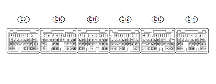
The standard voltage between each pair of ECM terminals is shown in the table below. In the table, first follow the information under "Condition". Look under "Terminal No. (Symbol)" for the terminals to be inspected. The standard voltage between the terminals is shown under "Specified Condition".
Use the illustration above as a reference for the ECM terminals.
|
Terminal No. (Symbol) |
Wiring Color |
Terminal Description |
Condition |
Specified Condition |
|---|---|---|---|---|
|
E10-26 (THO1) - E9-23 (ETHW) |
P - BR |
No. 1 ATF temperature sensor signal |
No. 1 ATF temperature: 115°C (239°F) or higher |
Below 1.5 V |
|
E10-34 (THO2) - E9-23 (ETHW) |
L - BR |
No. 2 ATF temperature sensor signal |
No. 2 ATF temperature: 115°C (239°F) or higher |
Below 1.5 V |
|
E11-9 (SL1+) - E11-8 (SL1-) |
R - V |
Shift solenoid valve SL1 signal |
1st, 2nd, 3rd or 4th gear |
Pulse generation |
|
E11-11 (SLU+) - E11-10 (SLU-) |
P - L |
Shift solenoid valve SLU signal |
2nd, 3rd, 4th, 5th or 6th gear (Flex lock-up on) |
Pulse generation |
|
E11-13 (SLT+) - E11-12 (SLT-) |
LG - Y |
Shift solenoid valve SLT signal |
Engine idling |
Pulse generation |
|
E12-8 (SL4+) - E12-7 (SL4-) |
SB - BE |
Shift solenoid valve SL4 signal |
3rd or 5th gear |
Pulse generation |
|
E12-14 (SL3+) - E12-13 (SL3-) |
B - W |
Shift solenoid valve SL3 signal |
2nd or 6th gear |
Pulse generation |
|
E12-15 (SL) - E11-1 (E1) |
R - W-B |
Shift solenoid valve SL signal |
All gears |
11 to 14 V |
|
E12-17 (R) - E11-1 (E1) |
V - W-B |
R shift position switch signal |
Ignition switch ON and shift lever in R |
11 to 14 V |
|
Ignition switch ON and shift lever not in R |
Below 1 V |
|||
|
E12-18 (P) - E11-1 (E1) |
GR - W-B |
P shift position switch signal |
Ignition switch ON and shift lever in P |
11 to 14 V |
|
Ignition switch ON and shift lever not in P |
Below 1 V |
|||
|
E12-20 (SL2+) - E12-19 (SL2-) |
GR - BE |
Shift solenoid valve SL2 signal |
4th, 5th or 6th gear |
Pulse generation |
|
E12-26 (SP2B) - E11-1 (E1) |
G - W-B |
Power source for sensor (fixed voltage) |
Ignition switch ON |
11 to 14 V |
|
E12-27 (D) - E11-1 (E1) |
R - W-B |
D shift position switch signal |
Ignition switch ON and shift lever in D, S, "+" or "-" |
11 to 14 V |
|
Ignition switch ON and shift lever not in D, S, "+" or "-" |
Below 1 V |
|||
|
E12-28 (N) - E11-1 (E1) |
G - W-B |
N shift position switch signal |
Ignition switch ON and shift lever in N |
11 to 14 V |
|
Ignition switch ON and shift lever not in N |
Below 1 V |
|||
|
E12-31 (NTO) - E11-1 (E1) |
W - W-B |
Transmission revolution sensor (NT) signal |
Engine idling |
Pulse generation |
|
E12-32 (NTB) - E11-1 (E1) |
Y - W-B |
Power source for sensor (fixed voltage) |
Ignition switch ON |
11 to 14 V |
|
E12-33 (SP2O) - E11-1 (E1) |
L - W-B |
Transmission revolution sensor (SP2) signal |
Vehicle driving |
Pulse generation |
|
E13-7 (SFTD) - E11-1 (E1) |
R - W-B |
Down-shift position switch signal |
Ignition switch ON and shift lever in S |
11 to 14 V |
|
Ignition switch ON and shift lever in "-" (Down-shift) |
Below 1 V |
|||
|
E13-8 (SFTU) - E11-1 (E1) |
G - W-B |
Up-shift position switch signal |
Ignition switch ON and shift lever in S |
11 to 14 V |
|
Ignition switch ON and shift lever in "+" (Up-shift) |
Below 1 V |
|||
|
E13-12 (STA) - E11-1 (E1) |
Y - W-B |
Starter assembly signal |
Cranking |
6 V or higher |
|
E13-13 (NSW) - E11-1 (E1) |
V - W-B |
Park/neutral position switch signal |
Ignition switch ON and shift lever in P or N |
Below 1 V |
|
Ignition switch ON and shift lever not in P or N |
11 to 14 V |
|||
|
E13-16 (STP) - E11-1 (E1) |
P - W-B |
Stop light switch assembly signal |
Brake pedal depressed |
7.5 to 14 V |
|
Brake pedal released |
0 to 1.5 V |
|||
|
E13-24 (SPD) - E11-1 (E1) |
R - W-B |
Vehicle speed signal |
Vehicle being driven |
Pulse generation |
|
E13-27 (CANH) - E11-1 (E1) |
B - W-B |
CAN communication line |
Ignition switch ON |
Pulse generation |
|
E13-28 (PWMS) - E11-1 (E1) |
P - W-B |
Pattern select switch signal |
Ignition switch ON and pattern select switch pushed |
Below 1 V |
|
Ignition switch ON and pattern select switch not pushed |
11 to 14 V |
|||
|
E13-32 (S) - E11-1 (E1) |
P - W-B |
S shift position switch signal |
Ignition switch ON and shift lever in S, "+" or "-" |
11 to 14 V |
|
Ignition switch ON and shift lever not in S, "+" or "-" |
Below 1 V |
|||
|
E13-35 (CANL) - E11-1 (E1) |
W - W-B |
CAN communication line |
Ignition switch ON |
Pulse generation |
|
E14-2 (BATT) - E11-1 (E1) |
L - W-B |
Battery (for measuring battery voltage and for ECM memory) |
Always |
11 to 14 V |
 Problem Symptoms Table
PROBLEM SYMPTOMS TABLE
HINT:
Use the table below to help determine the cause of problem symptoms.
If multiple suspected areas are listed, the potential causes of the symptoms
are lis ...
 Check Mode Procedure
CHECK MODE PROCEDURE
1. DESCRIPTION
(a) Check mode has a higher sensitivity to malfunctions and can detect malfunctions
that normal mode cannot detect. Check mode can also detect all the malfuncti ...
Other materials:
Meter Illumination is Always Dark
DESCRIPTION
In this circuit, the combination meter assembly receives auto dimmer signals
from the main body ECU (multiplex network body ECU) using the CAN communication
system (CAN V1 Bus). When the meter CPU receives an auto dimmer signal, it dims
the meter illumination (warning and indicato ...
Cargo Light Circuit
DESCRIPTION
The main body ECU (multiplex network body ECU) receives a cargo light information
signal from the deck light switch assembly and door courtesy light switch, and illuminates
the cargo light.
WIRING DIAGRAM
CAUTION / NOTICE / HINT
NOTICE:
Inspect the fuses for circuits r ...
Rear differential lock system
The rear differential lock system is provided for use only when wheel spinning
occurs in a ditch or on a slippery or rugged surface.
The rear differential lock system is effective in case one of the rear wheels
is spinning.
Press the RR DIFF LOCK switch to lock the rear differential.
At thi ...
