Toyota Tacoma (2015-2018) Service Manual: Television Camera
Components
COMPONENTS
ILLUSTRATION
Installation
INSTALLATION
PROCEDURE
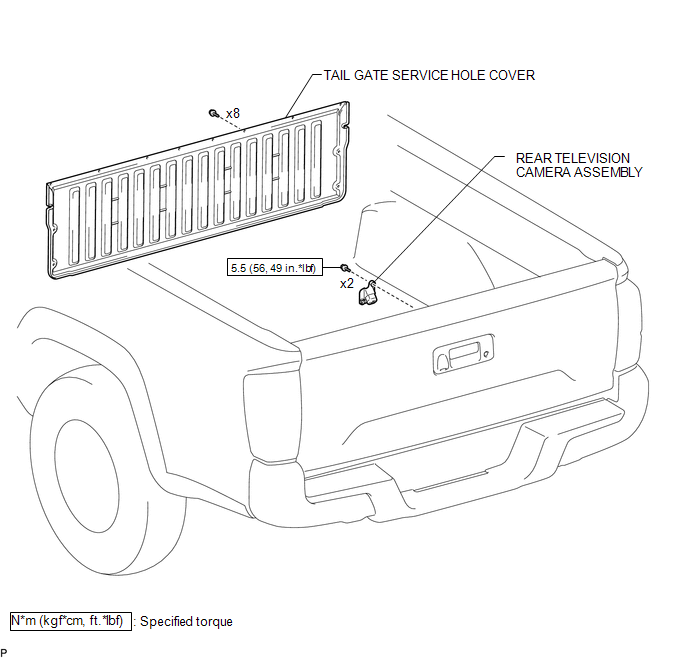
1. INSTALL REAR TELEVISION CAMERA ASSEMBLY
(a) Install the rear television camera assembly with the 2 bolts.
Torque:
5.5 N·m {56 kgf·cm, 49 in·lbf}
(b) Connect the connector.
2. INSTALL TAIL GATE SERVICE HOLE COVER
(See page .gif) )
)
3. INSTALL TAIL GATE PROTECTOR
(See page )
Removal
REMOVAL
PROCEDURE
1. REMOVE TAIL GATE PROTECTOR
(See page .gif) )
)
2. REMOVE TAIL GATE SERVICE HOLE COVER
(See page )
3. REMOVE REAR TELEVISION CAMERA ASSEMBLY
|
(a) Disconnect the connector. |
|
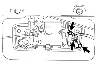
(b) Remove the 2 bolts and rear television camera assembly.
 Image from Camera for Rear View Monitor is Abnormal
DESCRIPTION
The display signal of the rear television camera assembly is transmitted to the
radio and display receiver assembly*1 or navigation receiver assembly*2.
*1: w/o Navigation Syste ...

Other materials:
Combination Meter ECU Communication Stop Mode
DESCRIPTION
Detection Item
Symptom
Trouble Area
Combination Meter ECU Communication Stop Mode
Either condition is met:
Communication stop for "Combination Meter" is indicated on the
"Communication Bus Ch ...
Terminals Of Ecu
TERMINALS OF ECU
1. AIR CONDITIONING AMPLIFIER ASSEMBLY
HINT:
Check from the rear of the connector while it is connected to the air conditioning
amplifier assembly.
Terminal No.
(Symbol)
Wiring Color
Terminal Description
Condition
Spe ...
Removal
REMOVAL
PROCEDURE
1. REMOVE INSTRUMENT PANEL SUB-ASSEMBLY
(See page
)
2. REMOVE NO. 3 HEATER TO REGISTER DUCT
3. REMOVE INSTRUMENT PANEL WIRE ASSEMBLY
(a) Using a screwdriver with its tip wrapped in protective tape, release
the 3 airbag connector locks.
Text in Illustr ...
