Toyota Tacoma (2015-2018) Service Manual: TC and CG Terminal Circuit
DESCRIPTION
The DLC3 circuit enables reading of Diagnostic Trouble Codes (DTCs) with no Techstream by connecting terminals TC and CG of the DLC3 connector.
Stored DTCs are displayed in blinking patterns of the CRUISE MAIN indicator light located on the combination meter.
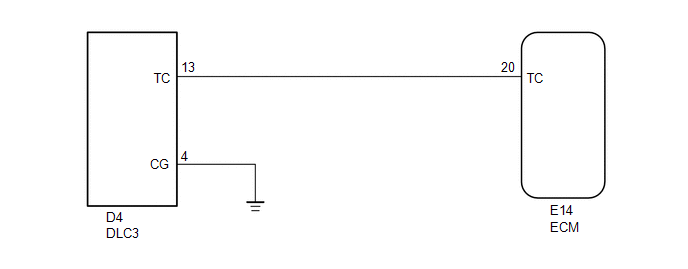
WIRING DIAGRAM
HINT:
When a particular warning light blinks continuously, a ground short in the wiring of terminal TC of the DLC3 or an internal ground short in the relevant ECU is suspected.
PROCEDURE
|
1. |
CHECK HARNESS AND CONNECTOR (TC of DLC3 - ECM) |
(a) Disconnect the E21 ECM connector.
(b) Measure the resistance according to the value(s) in the table below.
Standard Resistance:
|
Tester Connection |
Condition |
Specified Condition |
|---|---|---|
|
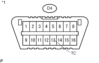
D4-13 (TC) - E14-20 (TC) |
Always |
Below 1 Ω |
(c) Reconnect the ECM connector.
| NG | .gif) |
REPAIR OR REPLACE HARNESS OR CONNECTOR |
|
.gif)
|
2. |
CHECK HARNESS AND CONNECTOR (TC of DLC3 - BODY GROUND) |
|
(a) Measure the resistance according to the value(s) in the table below. Standard Resistance:
|
|
| NG | |
REPAIR OR REPLACE HARNESS OR CONNECTOR |
|
|
3. |
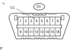
CHECK HARNESS AND CONNECTOR (CG of DLC3 - BODY GROUND) |
|
(a) Measure the resistance according to the value(s) in the table below. Standard Resistance:
|
|
| OK | |
REPLACE ECM |
| NG | |
REPAIR OR REPLACE HARNESS OR CONNECTOR |
 Cruise Main Indicator Light Circuit
DESCRIPTION
When the ECM detects a cruise control switch on signal from the cruise
control switch, the ECM sends the signal to the combination meter assembly
through CAN communication. ...

Other materials:
Input Speed Sensor Circuit No Signal (P0717,P07BF,P07C0)
DESCRIPTION
This sensor detects the rotation speed of the turbine which shows the input turbine
speed of the transmission. By comparing the input turbine speed signal (NT) with
the output shaft speed sensor signal (SP2), the ECM detects the shift timing of
the gears and appropriately controls ...
Terminals Of Ecu
TERMINALS OF ECU
1. CHECK AIR CONDITIONING AMPLIFIER ASSEMBLY (for Automatic Air Conditioning)
(See page )
2. CHECK AIR CONDITIONING AMPLIFIER ASSEMBLY (for Manual Air Conditioning)
(See page )
3. CHECK AIR CONDITIONING CONTROL ASSEMBLY (for Automatic Air Conditioning)
(See page )
4. CHECK ...
Front Radar Sensor Region Code Mismatch (C1A0A)
DESCRIPTION
The forward recognition camera receives necessary information from the millimeter
wave radar sensor assembly.
When the forward recognition camera judges that a millimeter wave radar sensor
assembly which is not compatible with the vehicle has been installed, DTC C1A0A
is stored.
...
