Toyota Tacoma (2015-2018) Service Manual: System Diagram
SYSTEM DIAGRAM
 Communication Table
|
Sender |
Receiver |
Signal |
Line |
|---|---|---|---|
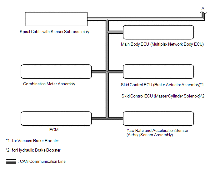
| *1: for Vacuum Brake Booster
*2: for Hydraulic Brake Booster |
|||
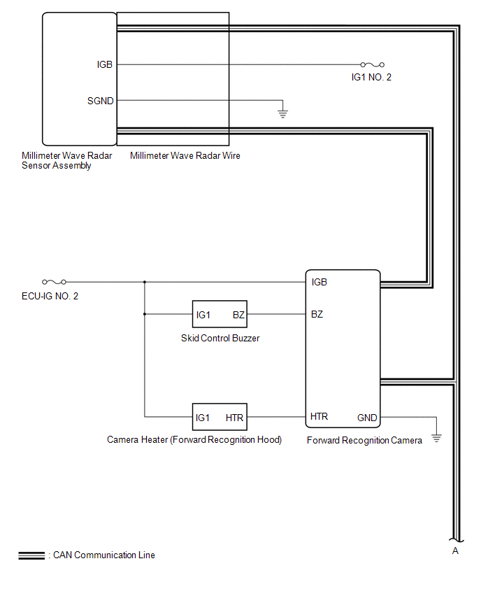
|
Millimeter Wave Radar Sensor Assembly |
Forward Recognition Camera |
|
CAN |
|
ECM |
Forward Recognition Camera |
|
CAN |
|
Forward Recognition Camera |
|
CAN |
|
Yaw Rate and Acceleration Sensor (Airbag Sensor Assembly) |
Forward Recognition Camera |
Vehicle yaw rate sensor signal |
CAN |
|
Main Body ECU (Multiplex Network Body ECU) |
Forward Recognition Camera |
Destination information signal |
CAN |
 System Description
SYSTEM DESCRIPTION
GENERAL DESCRIPTION
(a) The forward recognition camera processes the image captured by the monocular
camera to detect lane markers, vehicles, pedestrians, traffic signs, etc. Th ...
 How To Proceed With Troubleshooting
CAUTION / NOTICE / HINT
HINT:
Use these procedures to troubleshoot the forward recognition camera
system.
*: Use the Techstream.
PROCEDURE
1.
VEHICLE B ...
Other materials:
Dtc Check / Clear
DTC CHECK / CLEAR
1. CHECK DTC
(a) Connect the Techstream to the DLC3.
(b) Turn the ignition switch to ON.
(c) Turn the Techstream on.
(d) Enter the following menus: Body Electrical / Smart Access or Main Body /
Trouble Codes.
(e) Check the details of the DTC(s) (See page
).
2. CLEAR DTC ...
Removal
REMOVAL
PROCEDURE
1. REMOVE MILLIMETER WAVE RADAR WIRE
(a) for Type A:
(1) Disconnect the 2 connectors.
(2) Using a clip remover, disengage the 4 clamps to remove the millimeter
wave radar wire.
(b) for Type B:
(1) Disc ...
Seat Belt Buckle Switch LH Circuit Malfunction (B1656/38)
DESCRIPTION
The seat belt buckle switch LH circuit consists of the airbag sensor assembly
and the front seat inner belt assembly LH (seat belt buckle switch LH).
DTC B1655/37 is stored when a malfunction is detected in the seat belt buckle
switch LH circuit.
DTC No.
DTC ...
