Toyota Tacoma (2015-2018) Service Manual: System Diagram
SYSTEM DIAGRAM
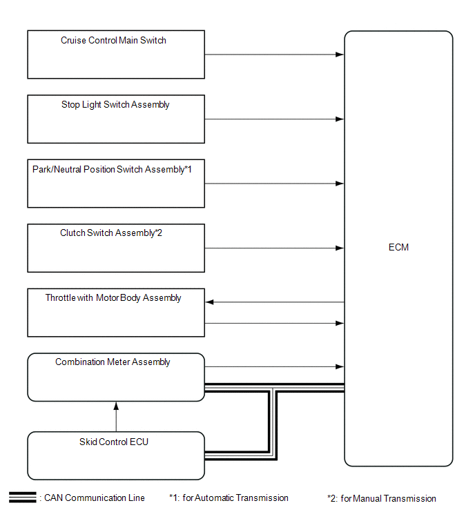 Communication Table
|
Sender |
Receiver |
Signal |
Line |
|---|---|---|---|
|
ECM |
Combination Meter Assembly |
Cruise main indicator light signal |
CAN |
|
Skid Control ECU |
ECM |
Vehicle stability control system operation signal |
CAN |
 System Description
SYSTEM DESCRIPTION
1. CRUISE CONTROL SYSTEM
The cruise control system makes it possible to drive at a desired speed without
using the accelerator pedal. ECM controls the throttle opening angle bas ...
 How To Proceed With Troubleshooting
CAUTION / NOTICE / HINT
HINT:
Use the following procedures to troubleshoot the cruise control system.
*: Use the Techstream.
PROCEDURE
1.
VEHICLE BROUGH ...
Other materials:
Installation
INSTALLATION
CAUTION / NOTICE / HINT
CAUTION:
Some of these service operations affect the SRS airbag system. Read
the precautionary notices concerning the SRS airbag system before servicing
(See page ).
If the side airbag was deployed, replace the front seat assembly with
...
Short to GND in Immobiliser System Power Source Circuit (B278A)
DESCRIPTION
When there is a short to GND in the power supply for the transponder key amplifier
of the engine switch, the certification ECU (smart key ECU assembly) stores this
DTC.
DTC Code
DTC Detection Condition
Trouble Area
DTC Output Confirmation ...
TC and CG Terminal Circuit
DESCRIPTION
Connecting terminals TC and CG of the DLC3 causes the ECU to display the DTC
by blinking the ABS warning light and slip indicator light.
WIRING DIAGRAM
CAUTION / NOTICE / HINT
NOTICE:
When replacing the skid control ECU (brake actuator assembly), perform zero point
calibration ...
