Toyota Tacoma (2015-2018) Service Manual: Stereo Component Amplifier
Components
COMPONENTS
ILLUSTRATION
.png)
ILLUSTRATION
Removal
REMOVAL
PROCEDURE
1. PRECAUTION
NOTICE:
After turning the ignition switch off, waiting time may be required before disconnecting the cable from the negative (-) battery terminal. Therefore, make sure to read the disconnecting the cable from the negative (-) battery terminal notices before proceeding with work.
Click here .gif)
2. DISCONNECT CABLE FROM NEGATIVE BATTERY TERMINAL
NOTICE:
When disconnecting the cable, some systems need to be initialized after the cable is reconnected.
Click here
3. REMOVE REAR SEATBACK ASSEMBLY RH
(See page )
4. REMOVE REAR SEATBACK ASSEMBLY LH
(See page )
5. REMOVE LUGGAGE COMPARTMENT SIDE TRAY LH
(See page )
6. REMOVE LUGGAGE COMPARTMENT SIDE TRAY RH
(See page )
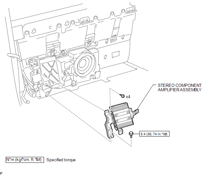
7. REMOVE STEREO COMPONENT AMPLIFIER ASSEMBLY
|
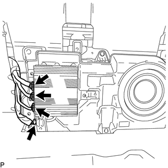
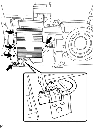
(a) Disconnect the 4 connectors. |
|
|
(b) Disengage the clamp. |
|
(c) Remove the bolt.
(d) Using a T20 "TORX" socket wrench, remove the 4 screws and stereo component amplifier assembly.
Installation
INSTALLATION
PROCEDURE
1. INSTALL STEREO COMPONENT AMPLIFIER ASSEMBLY
(a) Using a T20 "TORX" socket wrench, install the stereo component amplifier assembly with the 4 screws.
(b) Install the bolt.
Torque:
8.4 N·m {86 kgf·cm, 74 in·lbf}
(c) Engage the clamp.
(d) Connect the 4 connectors.
2. INSTALL LUGGAGE COMPARTMENT SIDE TRAY RH
(See page .gif) )
)
3. INSTALL LUGGAGE COMPARTMENT SIDE TRAY LH
(See page )
4. INSTALL REAR SEATBACK ASSEMBLY LH
(See page )
5. INSTALL REAR SEATBACK ASSEMBLY RH
(See page )
6. CONNECT CABLE TO NEGATIVE BATTERY TERMINAL
Torque:
5.4 N·m {55 kgf·cm, 48 in·lbf}
NOTICE:
When disconnecting the cable, some systems need to be initialized after the cable is reconnected.
Click here
 Steering Pad Switch
Components
COMPONENTS
ILLUSTRATION
*1
STEERING PAD SWITCH ASSEMBLY
-
-
Removal
REMOVAL
PROCEDURE
1. REMOVE STEERING PAD
(See page )
...

Other materials:
Clearance Sonar Main Switch Circuit
DESCRIPTION
The back sonar or clearance sonar switch assembly is installed at the base of
the driver side of the instrument panel.
When the back sonar or clearance sonar switch assembly is turned on, an on signal
is sent to the clearance warning ECU assembly. The intuitive parking assist syste ...
Cruise Control Switch Circuit
DESCRIPTION
The cruise control main switch is used to turn the dynamic radar cruise control
system on and off, as well as operate 7 functions: SET, - (COAST), TAP-DOWN, RES
(RESUME), + (ACCEL), TAP-UP and CANCEL.
The SET, TAP-DOWN and - (COAST) functions, and the RES (RESUME), TAP-UP and +
( ...
Inspection
INSPECTION
PROCEDURE
1. INSPECT REAR AXLE SHAFT
(a) Using a dial indicator, measure the runout of the shaft and flange.
Maximum runout:
Shaft runout: 1.5 mm (0.0591 in.)
Flange runout: 0.05 mm (0.0020 in.)
If the rear axle shaft or flange is damaged or worn, or the runout is greater
than ...
