Toyota Tacoma (2015-2018) Service Manual: Steering Pad Switch
Components
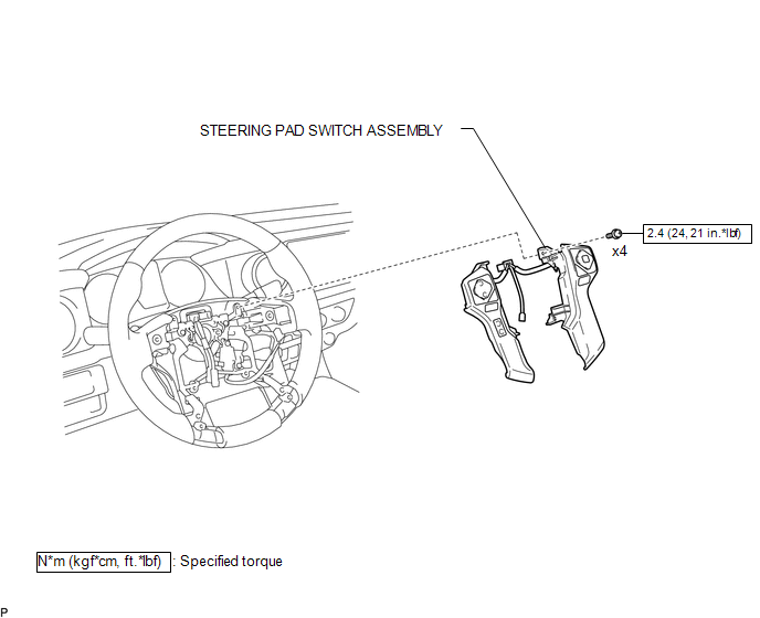
COMPONENTS
ILLUSTRATION
Removal
REMOVAL
PROCEDURE
1. REMOVE STEERING PAD
(See page .gif) )
)
2. REMOVE STEERING PAD SWITCH ASSEMBLY
|
(a) Disconnect the 2 connectors. |
|
.png)
(b) Disengage the 2 clamps.
(c) Remove the 4 screws.
|
(d) Disengage the 6 guides and 2 claws to remove the steering pad switch assembly. NOTICE: Disengage the 2 guides on the upper part of the steering pad switch assembly first. |
|
.png)
Inspection
INSPECTION
PROCEDURE
1. INSPECT STEERING PAD SWITCH ASSEMBLY
(See page .gif) )
)
Installation
INSTALLATION
PROCEDURE
1. INSTALL STEERING PAD SWITCH ASSEMBLY
(a) Engage the 6 guides and 2 claws to install the steering pad switch assembly.
(b) Install the 4 screws.
Torque:
2.4 N·m {24 kgf·cm, 21 in·lbf}
(c) Engage the 2 clamps.
(d) Connect the 2 connectors.
2. INSTALL STEERING PAD
(See page .gif) )
)
 Speed Signal Circuit
DESCRIPTION
The combination meter assembly receives the vehicle speed signal from this circuit.
The wheel speed sensors produce an output that varies according to the vehicle speed.
The wheel spe ...
 Mirror
...
Other materials:
Disposal
DISPOSAL
PROCEDURE
1. DISPOSE OF FRONT SHOCK ABSORBER ASSEMBLY
(a) Fully extend the shock absorber piston rod, and fix it at an angle in a vise
or similar tool.
(b) Using a drill or similar tool, slowly make a hole in the shaded area shown
in the illustration, and discharge the gas inside. ...
Personal Light Assembly
Components
COMPONENTS
ILLUSTRATION
Installation
INSTALLATION
PROCEDURE
1. INSTALL MAP LIGHT BULB
(a) Install the 2 map light bulbs to the 2 map light sockets.
(b) Turn the 2 map light sockets with 2 map light bulbs in the direction
indicated by the arrow shown in the ill ...
Removal
REMOVAL
PROCEDURE
1. REMOVE REFRIGERANT FROM REFRIGERATION SYSTEM
2. REMOVE AIR CONDITIONER PRESSURE SENSOR
(a) Disconnect the connector.
(b) Using a 27 mm deep socket wrench, remove the air conditioner pressure
sensor.
T ...
