Toyota Tacoma (2015-2018) Service Manual: Sound Signal Circuit between Radio Receiver and Stereo Component Amplifier
DESCRIPTION
The navigation receiver assembly sends a sound signal to the stereo component amplifier assembly via this circuit.
The sound signal that has been sent is amplified by the stereo component amplifier assembly, and then is sent to the speakers.
If there is an open or short in the circuit, sound cannot be heard from the speakers even if there is no malfunction in the stereo component amplifier assembly or speakers.
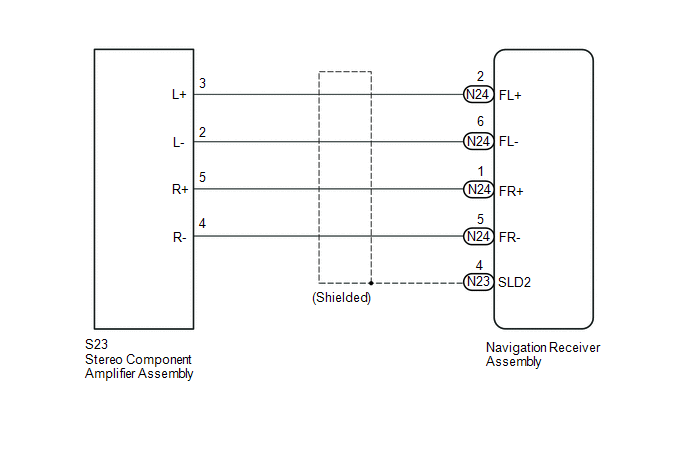
WIRING DIAGRAM
PROCEDURE
|
1. |
CHECK HARNESS AND CONNECTOR (NAVIGATION RECEIVER ASSEMBLY - STEREO COMPONENT AMPLIFIER ASSEMBLY) |
(a) Disconnect the N23 and N24 navigation receiver assembly connector.
(b) Disconnect the S23 stereo component amplifier assembly connector.
(c) Measure the resistance according to the value(s) in the table below.
Standard Resistance:
|
Tester Connection |
Condition |
Specified Condition |
|---|---|---|
|
S23-3 (L+) - N24-2 (FL+) |
Always |
Below 1 Ω |
|
S23-2 (L-) - N24-6 (FL-) |
Always |
Below 1 Ω |
|
S23-5 (R+) - N24-1 (FR+) |
Always |
Below 1 Ω |
|
S23-4 (R-) - N24-5 (FR-) |
Always |
Below 1 Ω |
|
S23-3 (L+) - Body ground |
Always |
10 kΩ or higher |
|
S23-2 (L-) - Body ground |
Always |
10 kΩ or higher |
|
S23-5 (R+) - Body ground |
Always |
10 kΩ or higher |
|
S23-4 (R-) - Body ground |
Always |
10 kΩ or higher |
|
N23-4 (SLD2) - Body ground |
Always |
10 kΩ or higher |
| OK | .gif) |
PROCEED TO NEXT SUSPECTED AREA SHOWN IN PROBLEM SYMPTOMS TABLE |
| NG | |
REPAIR OR REPLACE HARNESS OR CONNECTOR |
 Speaker Circuit
DESCRIPTION
If there is a short in a speaker circuit, the stereo component amplifier assembly*1
or navigation receiver assembly*2 detects it and stops output to the speakers.
Thus sound cannot be ...
 Data Signal Circuit between Stereo Jack Adapter and Extension Module
DESCRIPTION
The No. 1 stereo jack adapter assembly sends the sound data signal or image data
signal from a USB device to the navigation receiver assembly via this circuit.
WIRING DIAGRAM
PROCED ...
Other materials:
Removal
REMOVAL
PROCEDURE
1. PRECAUTION
CAUTION:
Be sure to read Precaution thoroughly before servicing (See page
).
NOTICE:
After turning the ignition switch off, waiting time may be required before disconnecting
the cable from the negative (-) battery terminal. Therefore, make sure to read the
...
Data List / Active Test
DATA LIST / ACTIVE TEST
1. DATA LIST
NOTICE:
In the table below, the values listed under "Normal Condition" are reference
values. Do not depend solely on these reference values when deciding whether a part
is faulty or not.
HINT:
Using the Techstream to read the Data List allows t ...
Illumination for Panel Switch does not Come on with Tail Switch ON
PROCEDURE
1.
CHECK VEHICLE SIGNAL (OPERATION CHECK)
(a) Enter the "Vehicle Signal Check Mode" screen. Refer to Check Vehicle Signal
in Operation Check (See page ).
(b) Check that the display changes between ON and OFF according to the light
control ...
