Toyota Tacoma (2015-2018) Service Manual: Some Alarm Functions do not Operate
DESCRIPTION
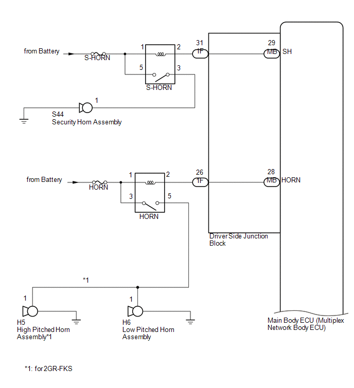
When the alarm sounds, the following alarm functions operate: the roof console box assembly and No. 1 room light assembly illuminates, and the headlights, taillights and hazard lights flash, and the security horn and vehicle horn sound intermittently.
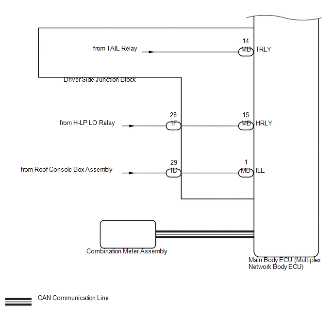
WIRING DIAGRAM
CAUTION / NOTICE / HINT
NOTICE:
- Before replacing the main body ECU (multiplex network body ECU), refer
to Registration (See page
.gif) ).*1
).*1
- *1: w/ Smart Key System
- Inspect the fuses for circuits related to this system before performing the following procedure.
PROCEDURE
|
1. |
CHECK THEFT DETERRENT SYSTEM OPERATION |
(a) Open the driver side window.
(b) Set the theft deterrent system.
(1) Close all doors and the hood.
(2) Lock the doors using wireless operation*1, key linked operation or entry operation*2.
- *1: w/ Wireless Door Lock System
- *2: w/ Smart Key System
(3) Wait for 30 seconds or more.
(c) After 30 seconds have elapsed, check that the security indicator light changes from illuminated to flashing.
(d) Unlock the driver door using the door lock knob.
(e) Check that each alarm component operates correctly.
Result|
Result |
Proceed to |
|---|---|
|
Security horn is not activated |
A |
|
Vehicle horn is not activated |
B |
|
Headlights, taillights or hazard lights are not activated |
C |
|
Interior lights are not activated |
D |
| B | .gif) |
GO TO STEP 9 |
| C | |
GO TO LIGHTING SYSTEM |
| D | |
GO TO LIGHTING SYSTEM |
|
.gif)
|
2. |
PERFORM ACTIVE TEST USING TECHSTREAM (SECURITY HORN) |
(a) Connect the Techstream to the DLC3.
(b) Turn the ignition switch to ON.
(c) Turn the Techstream on.
(d) Enter the following menus: Body Electrical / Main Body / Active Test.
(e) Perform the Active Test according to the display on the Techstream.
Main Body|
Tester Display |
Test Part |
Control Range |
Diagnostic Note |
|---|---|---|---|
|
Security Horn |
Security horn assembly |
OFF/ON |
- |
OK:
The security horn assembly sounds and stops correctly when operated through the Techstream.
| OK | |
REPLACE MAIN BODY ECU (MULTIPLEX NETWORK BODY ECU) |
|
|
3. |
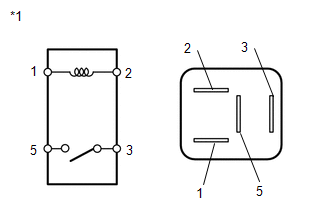
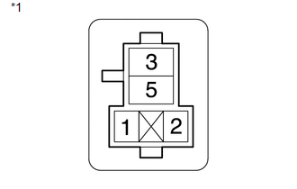
INSPECT S-HORN RELAY |
(a) Remove the S-HORN relay from the engine room relay block.
|
(b) Measure the resistance according to the value(s) in the table below. Standard Resistance:
|
|
| NG | |
REPLACE S-HORN RELAY |
|
|
4. |
CHECK HARNESS AND CONNECTOR (BATTERY - S-HORN RELAY) |
(a) Remove the S-HORN relay from the engine room relay block assembly.
|
(b) Measure the voltage according to the value(s) in the table below. Standard Voltage:
|
|
| NG | |
REPAIR OR REPLACE HARNESS OR CONNECTOR |
|
|
5. |
INSPECT SECURITY HORN ASSEMBLY |
(a) Remove the security horn assembly (See page
).
(b) Inspect the security horn assembly (See page
).
| NG | |
REPLACE SECURITY HORN ASSEMBLY |
|
|
6. |
CHECK HARNESS AND CONNECTOR (S-HORN RELAY - SECURITY HORN ASSEMBLY) |
(a) Remove the S-HORN relay from the engine room relay block assembly.
(b) Disconnect the S44 security horn assembly connector.
(c) Measure the resistance according to the value(s) in the table below.
Standard Resistance:
|
Tester Connection |
Condition |
Specified Condition |
|---|---|---|
|
3 (S-HORN relay holder) - S44-1 |
Always |
Below 1 Ω |
|
3 (S-HORN relay holder) or S44-1 - Body ground |
Always |
10 kΩ or higher |
| NG | |
REPAIR OR REPLACE HARNESS OR CONNECTOR |
|
|
7. |
CHECK HARNESS AND CONNECTOR (S-HORN RELAY - DRIVER SIDE JUNCTION BLOCK) |
(a) Remove the S-HORN relay from the engine room relay block assembly.
(b) Disconnect the 1F driver side junction block connector.
(c) Measure the resistance according to the value(s) in the table below.
Standard Resistance:
|
Tester Connection |
Condition |
Specified Condition |
|---|---|---|
|
2 (S-HORN relay holder) - 1F-31 |
Always |
Below 1 Ω |
|
2 (S-HORN relay holder) or 1F-31 - Body ground |
Always |
10 kΩ or higher |
| NG | |
REPAIR OR REPLACE HARNESS OR CONNECTOR |
|
|
8. |
INSPECT DRIVER SIDE JUNCTION BLOCK |
(a) Remove the main body ECU (multiplex network body ECU) (See page
).
(b) Disconnect the driver side junction block connector.
(c) Measure the resistance according to the value(s) in the table below.
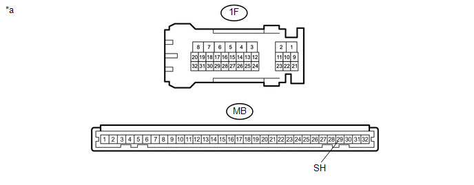 Text in Illustration
|
*a |
Component without harness connected (Driver Side Junction Block ) |
- |
- |
Standard Resistance:
|
Tester Connection |
Condition |
Specified Condition |
|---|---|---|
|
1F-31 - MB-29 (SH) |
Always |
Below 1 Ω |
| OK | |
REPLACE MAIN BODY ECU (MULTIPLEX NETWORK BODY ECU) |
| NG | |
REPLACE DRIVER SIDE JUNCTION BLOCK |
|
9. |
CHECK HORN OPERATION |
(a) Press the horn switch and check if the horn sounds.
OK:
Horn sounds
| NG | |
GO TO HORN SYSTEM |
|
|
10. |
INSPECT DRIVER SIDE JUNCTION BLOCK |
(a) Remove the main body ECU (multiplex network body ECU) (See page
).
(b) Disconnect the driver side junction block connector.
(c) Measure the resistance according to the value(s) in the table below.
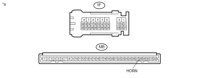 Text in Illustration
|
*a |
Component without harness connected (Driver Side Junction Block) |
- |
- |
Standard Resistance:
|
Tester Connection |
Condition |
Specified Condition |
|---|---|---|
|
1F-26 - MB-28 (HORN) |
Always |
Below 1 Ω |
| OK | |
REPLACE MAIN BODY ECU (MULTIPLEX NETWORK BODY ECU) |
| NG | |
REPLACE DRIVER SIDE JUNCTION BLOCK |
 Theft Deterrent System Unexpectedly Sets Itself
DESCRIPTION
A situation in which the theft deterrent system unexpectedly sets itself can
be caused when the main body ECU (multiplex network body ECU) cannot detect whether
a door is open or clos ...
 While Alarm is Armed, Battery is Reconnected but Alarm does not Sound
DESCRIPTION
While the alarm is armed, the EEPROM inside the main body ECU (multiplex network
body ECU) will remember the armed state even if the battery is disconnected, and
the alarm will sound ...
Other materials:
Components
COMPONENTS
ILLUSTRATION
*A
for Double Cab
*B
for Access Cab
*1
AUTO HIGH BEAM SWITCH
*2
COWL SIDE TRIM BOARD LH
*3
FRONT DOOR SCUFF PLATE LH
*4
HOOD LOC ...
Transmitter ID not Received in Main Mode (C2126/26)
DESCRIPTION
After all transmitter IDs are registered, DTC C2126/26 is stored in the tire
pressure warning ECU and receiver and the tire pressure warning light blinks for
1 minute and then illuminates.
When the tire pressure warning ECU and receiver successfully receives radio waves
from all ...
Removal
REMOVAL
PROCEDURE
1. REMOVE FRONT DOOR SCUFF PLATE LH (for Double Cab)
2. REMOVE FRONT DOOR SCUFF PLATE LH (for Access Cab)
3. REMOVE COWL SIDE TRIM BOARD LH
4. REMOVE INSTRUMENT CLUSTER CENTER FINISH PANEL SUB-ASSEMBLY
5. REMOVE INSTRUMENT CLUSTER FINISH PANEL ASSEMBLY
6. ...
