Toyota Tacoma (2015-2018) Service Manual: Room Light Assembly
Components
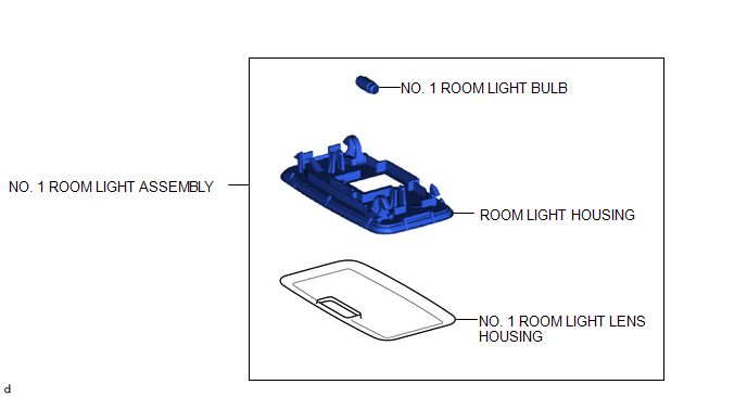
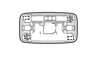
COMPONENTS
ILLUSTRATION
Removal
REMOVAL
PROCEDURE
1. REMOVE NO. 1 ROOM LIGHT ASSEMBLY
|
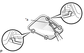
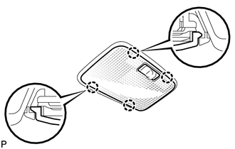
(a) Using a screwdriver with its tip wrapped in protective tape, disengage the 4 claws to remove the No. 1 room light lens. Text in Illustration
|
|
(b) Using a screwdriver with its tip wrapped in protective tape, disengage the 2 claws and 2 guides to separate the No. 1 room light housing as shown in the illustration.
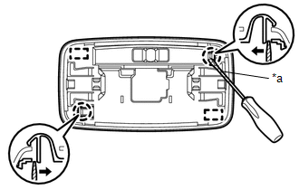 Text in Illustration
|
*a |
Protective Tape |
.png) |
Push |
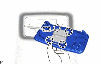
(c) Disengage the guide to separate the wire harness.
|
(d) Disengage the 4 claws to separate the No. 1 room light housing from the room light switch base. |
|
2. REMOVE NO. 1 ROOM LIGHT BULB
(a) Remove the No. 1 room light bulb.
Installation
INSTALLATION
PROCEDURE
1. INSTALL NO. 1 ROOM LIGHT BULB
(a) Install the No. 1 room light bulb.
2. INSTALL NO. 1 ROOM LIGHT ASSEMBLY
(a) Engage the 4 claws to install the No. 1 room light housing to the room light switch base.
(b) Engage the guide to install the wire harness.
|
(c) Engage the 2 guides and 2 claws to install the No. 1 room light housing. |
|
|
(d) Engage the 4 claws to install the No. 1 room light lens. |
|
 Rear Door Courtesy Switch
Inspection
INSPECTION
PROCEDURE
1. INSPECT REAR DOOR COURTESY SWITCH
(a) Check the resistance.
(1) Measure the resistance using an ohmmeter, and check the results in accordance
with the value ...
 Side Turn Signal Light Assembly
Components
COMPONENTS
ILLUSTRATION
Removal
REMOVAL
CAUTION / NOTICE / HINT
HINT:
Use the same procedure for both the RH and LH sides.
The procedure described below is for the ...
Other materials:
Ambient Temperature Sensor Circuit (B1412/12)
DESCRIPTION
The ambient temperature sensor is installed in front of the condenser to detect
the ambient temperature which is used to control the air conditioning system AUTO
mode. This sensor is connected to the air conditioning amplifier assembly and detects
fluctuations in the ambient tempe ...
Low Output Signal of Front Speed Sensor RH (Test Mode DTC) (C1271,C1272,C1401,C1402)
DESCRIPTION
The speed sensor detects the wheel speed and sends the appropriate signals to
the skid control ECU (master cylinder solenoid). These signals are used for brake
control.
The speed sensor rotors have rows of alternating N and S magnetic poles and their
magnetic fields change when t ...
SD Card Communication Malfunction (B158C)
DESCRIPTION
The navigation receiver assembly stores this DTC when the SD card cannot be mounted
when inserted into the SD card slot.
DTC Code
DTC Detection Condition
Trouble Area
B158C
The SD card cannot be mounted when inserted into t ...
