Toyota Tacoma (2015-2018) Service Manual: Removal
REMOVAL
CAUTION / NOTICE / HINT
NOTICE:
Release the vacuum from booster by depressing the brake pedal several times.
Then remove the brake master cylinder from brake booster.
PROCEDURE
1. PRECAUTION
NOTICE:
After turning the ignition switch off, waiting time may be required before disconnecting the cable from the negative (-) battery terminal. Therefore, make sure to read the disconnecting the cable from the negative (-) battery terminal notices before proceeding with work.
Click here .gif)
2. DISCONNECT CABLE FROM NEGATIVE BATTERY TERMINAL
NOTICE:
When disconnecting the cable, some systems need to be initialized after the cable is reconnected.
Click here
3. REMOVE LOWER NO. 1 INSTRUMENT PANEL AIRBAG ASSEMBLY
Click here
4. REMOVE BRAKE MASTER CYLINDER SUB-ASSEMBLY
Click here
5. SEPARATE MASTER CYLINDER PUSH ROD CLEVIS
Click here
6. REMOVE BRAKE BOOSTER ASSEMBLY
|
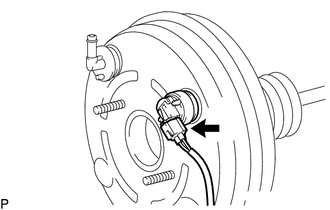
(a) Disconnect the vacuum warning switch assembly connector. (for 2GR-FKS) |
|
|
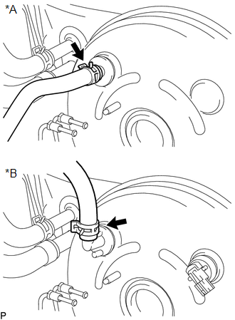
(b) Disconnect the vacuum hose from the brake booster assembly. Text in Illustration
|
|
|
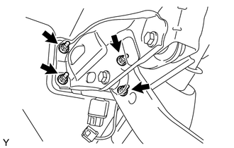
(c) Remove the 4 nuts, and pull out the brake booster assembly. |
|
(d) Remove the gasket from the brake booster assembly.
(e) Loosen the lock nut and then remove the push rod clevis.
7. REMOVE BRAKE VACUUM CHECK VALVE ASSEMBLY
|
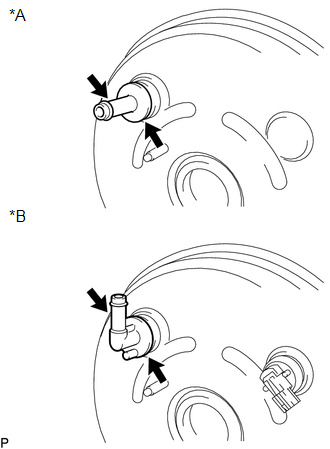
(a) Remove the vacuum check valve from the brake booster assembly. Text in Illustration
|
|
(b) Remove the grommet from the brake booster assembly.
8. REMOVE VACUUM WARNING SWITCH ASSEMBLY (for 2GR-FKS)
Click here
 On-vehicle Inspection
ON-VEHICLE INSPECTION
PROCEDURE
1. CHECK BRAKE BOOSTER ASSEMBLY
(a) Airtightness check.
Text in Illustration
*a
Correct
...
 Inspection
INSPECTION
PROCEDURE
1. INSPECT BRAKE VACUUM CHECK VALVE ASSEMBLY
(a) Check that there is ventilation from the booster to the engine, and
no ventilation from the engine to the booste ...
Other materials:
Pressure Control Solenoid "D" Circuit Open (P271313)
DESCRIPTION
Refer to the system description for DTC P27137F (See page
).
DTC No.
DTC Detection Condition
Trouble Area
SAE
P271313
Open or short is detected in shift solenoid valve SLT circuit for 1 second
or more while d ...
Center Airbag Sensor Communication Stop Mode
DESCRIPTION
Detection Item
Symptom
Trouble Area
Center Airbag Sensor Communication Stop Mode
Either condition is met:
Communication stop for "Airbag" is indicated on the "Communication
Bus Check" sc ...
Terminals Of Ecu
TERMINALS OF ECU
1. CHECK DRIVER SIDE JUNCTION BLOCK AND MAIN BODY ECU (MULTIPLEX NETWORK BODY
ECU)
(a) Disconnect the MB main body ECU (multiplex network body ECU) connectors.
(b) Measure the voltage and resistance according to the value(s) in the table
below.
HINT:
Measure the values on ...
