Toyota Tacoma (2015-2018) Service Manual: Removal
REMOVAL
PROCEDURE
1. REMOVE AIR CONDITIONING CONTROL ASSEMBLY (for Automatic Air Conditioning System)
Click here .gif)
2. REMOVE AIR CONDITIONING CONTROL ASSEMBLY (for Manual Air Conditioning System)
Click here
3. REMOVE LOWER NO. 2 INSTRUMENT PANEL AIRBAG ASSEMBLY
Click here
4. REMOVE INSTRUMENT LOWER PANEL ASSEMBLY
Click here
5. REMOVE FRONT CONSOLE BOX
Click here
6. REMOVE NO. 2 INSTRUMENT PANEL GARNISH SUB-ASSEMBLY
Click here
7. REMOVE INSTRUMENT PANEL LOWER CENTER FINISH PANEL
Click here
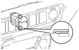
8. REMOVE REAR NO. 2 POWER WINDOW REGULATOR SWITCH ASSEMBLY
|
(a) Disengage the 2 claws to remove the rear No. 2 power window regulator switch assembly. |
|
 Inspection
INSPECTION
PROCEDURE
1. INSPECT REAR NO. 2 POWER WINDOW REGULATOR SWITCH ASSEMBLY
*a
Component without harness connected
(Rear No. 2 Power Window Regulator Switch Assembl ...
 Installation
INSTALLATION
PROCEDURE
1. INSTALL REAR NO. 2 POWER WINDOW REGULATOR SWITCH ASSEMBLY
(a) Engage the 2 claws to install the rear No. 2 power window regulator switch
assembly.
2. INSTALL INSTRUMENT ...
Other materials:
Radio Antenna
Components
COMPONENTS
ILLUSTRATION
Removal
REMOVAL
PROCEDURE
1. REMOVE ROOF HEADLINING ASSEMBLY (for Double Cab)
(See page )
2. REMOVE ROOF HEADLINING ASSEMBLY (for Access Cab)
(See page )
3. REMOVE ANTENNA ASSEMBLY WITH HOLDER
(a) Disengage the 3 clamps.
(b) Remove the nut.
...
Lost Communication with Cruise Control Front Distance Range Sensor (U0235)
DESCRIPTION
The millimeter wave radar sensor assembly is connected to the skid control ECU
(master cylinder solenoid)*1 or skid control ECU (brake actuator assembly)*2 via
CAN communication. If communication with the skid control ECU (master cylinder solenoid)*1
or skid control ECU (brake act ...
Operation History List
OPERATION HISTORY LIST
NOTICE:
The cause of a malfunction is stored in the RAM or EEPROM in the certification
ECU (smart key ECU assembly). As the cause of a malfunction stored in the
RAM will be cleared when the cable is disconnected from the negative (-)
battery terminal, do ...
