Toyota Tacoma (2015-2018) Service Manual: Removal
REMOVAL
CAUTION / NOTICE / HINT
CAUTION:
Some of these service operations affect the SRS airbag system. Read the precautionary
notices concerning the SRS airbag system before servicing (See page
.gif) ).
).
HINT:
- Use the same procedure for both the RH and LH sides.
- The procedure described below is for the LH side.
PROCEDURE
1. PRECAUTION
CAUTION:
Be sure to read Precaution thoroughly before servicing (See page
).
NOTICE:
After turning the ignition switch off, waiting time may be required before disconnecting the cable from the negative (-) battery terminal. Therefore, make sure to read the disconnecting the cable from the negative (-) battery terminal notices before proceeding with work.
Click here
2. DISCONNECT CABLE FROM NEGATIVE BATTERY TERMINAL
CAUTION:
Wait at least 90 seconds after disconnecting the cable from the negative (-) battery terminal to disable the SRS system.
NOTICE:
When disconnecting the cable, some systems need to be initialized after the cable is reconnected.
Click here
3. REMOVE RADIATOR GRILLE
4. REMOVE RADIATOR SIDE DEFLECTOR
5. REMOVE FRONT AIRBAG SENSOR
(a) Check that the ignition switch is off.
(b) Check that the cable is disconnected from the negative (-) battery terminal.
CAUTION:
Wait at least 90 seconds after disconnecting the cable from the negative (-) battery terminal to disable the SRS system.
|
(c) Remove the 2 bolts. |
|
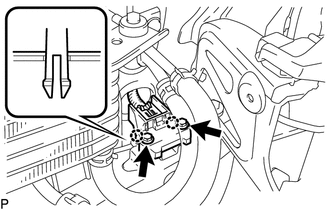
(d) Disengage the 2 claws.
NOTICE:
Loosen the bolt while holding the front airbag sensor because the front airbag sensor 2 claws (stopper) is easily damaged.
(e) Disconnect the connector to remove the front airbag sensor LH.
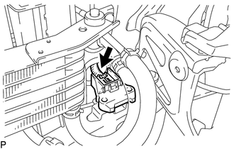
NOTICE:
When disconnecting any airbag connector, take care not to damage the airbag wire harness.
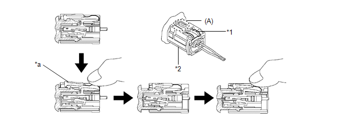
(1) Push down the white housing lock and slide the yellow CPA (At this time, the connector cannot be disconnected yet).
 Text in Illustration
|
*1 |
Housing Lock |
*2 |
CPA |
|
*a |
Connector Lock is Released |
- |
- |
(2) Push down the white housing lock again and disconnect the connector and remove the front airbag sensor LH.
NOTICE:
Do not push down the part (A) shown in the illustration when disconnecting.
(3) After disconnecting the connector, check that the position of the white housing lock is correct as shown in the illustration.
.png)
|
*a |
Incorrect |
*b |
Correct |
 Installation
INSTALLATION
CAUTION / NOTICE / HINT
CAUTION:
Some of these service operations affect the SRS airbag system. Read the precautionary
notices concerning the SRS airbag system before servicing (See ...

Other materials:
Installation
INSTALLATION
CAUTION / NOTICE / HINT
HINT:
Perform "Inspection After Repairs" after replacing the fuel pump assembly (See
page ).
PROCEDURE
1. SET FUEL PUMP ASSEMBLY
HINT:
Perform "Inspection After Repairs" after replacing the fuel pump assembly (See
page ).
...
Master Cylinder Pressure Sensor Output Malfunction (Test Mode DTC) (C1281,...,C1458)
DESCRIPTION
DTC Code
DTC Detection Condition
Trouble Area
C1281
Stored only during test mode.
Master cylinder pressure sensor circuit
Skid control ECU, master cylinder pressure sensor (master cylinder
s ...
Removal
REMOVAL
PROCEDURE
1. REMOVE ENGINE ASSEMBLY
(See page )
2. REMOVE IGNITION COIL ASSEMBLY
3. REMOVE ENGINE OIL LEVEL DIPSTICK GUIDE
4. REMOVE CAMSHAFT TIMING OIL CONTROL SOLENOID ASSEMBLY (for Intake Side of Bank
1)
5. REMOVE CAMSHAFT TIMING OIL CONTROL SOLENOID ASSEMBLY (for Exha ...
