Toyota Tacoma (2015-2018) Service Manual: Removal
REMOVAL
PROCEDURE
1. PRECAUTION
NOTICE:
After turning the ignition switch off, waiting time may be required before disconnecting the cable from the negative (-) battery terminal. Therefore, make sure to read the disconnecting the cable from the negative (-) battery terminal notices before proceeding with work.
Click here .gif)
2. RECOVER REFRIGERANT FROM REFRIGERATION SYSTEM
Click here
3. DISCONNECT CABLE FROM NEGATIVE BATTERY TERMINAL
NOTICE:
When disconnecting the cable, some systems need to be initialized after the cable is reconnected.
Click here
4. REMOVE RADIATOR ASSEMBLY (for 2TR-FE)
Click here
5. REMOVE RADIATOR ASSEMBLY (for 2GR-FKS)
Click here
6. DISCONNECT DISCHARGE HOSE SUB-ASSEMBLY
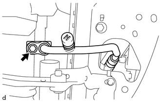
(a) Remove the bolt to disconnect the discharge hose sub-assembly from the cooler condenser assembly.
(b) Remove the O-ring from the discharge hose sub-assembly.
NOTICE:
Seal the openings of the disconnected parts using vinyl tape to prevent moisture and foreign matter from entering.
7. DISCONNECT AIR CONDITIONING TUBE ASSEMBLY
|
(a) Remove the bolt to disconnect the air conditioning tube assembly from the cooler condenser assembly. |
|
(b) Remove the O-ring from the air conditioning tube assembly.
NOTICE:
Seal the openings of the disconnected parts using vinyl tape to prevent moisture and foreign matter from entering.
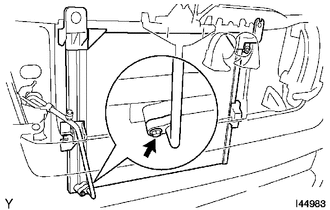
8. REMOVE COOLER CONDENSER ASSEMBLY
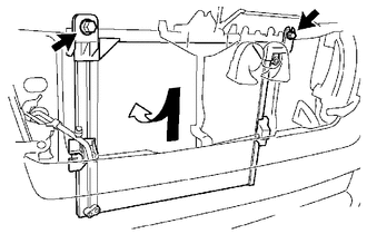
(a) Remove the 2 bolts.
(b) Lift the cooler condenser assembly up, disengage the fitting of the condenser lower bracket to remove the cooler condenser assembly from the rear side of the vehicle.
|
(c) Disengage the 2 claws to remove the 2 condenser upper brackets. |
|
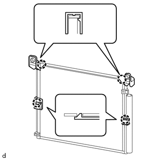
(d) Disengage the 2 claws to remove the 2 condenser lower brackets.
(e) Remove the cooler condenser assembly.
HINT:
At the time of installation, please refer to the following instructions. If installing a new condenser, add compressor oil to the condenser.
Compressor oil:
PSD1 or equivalent
Add 40 cc (1.4 fl.oz.)
 On-vehicle Inspection
ON-VEHICLE INSPECTION
PROCEDURE
1. INSPECT COOLER CONDENSER ASSEMBLY
(a) If the fins of the cooler condenser assembly are dirty, clean them with water
and dry them with compressed air.
NOTICE:
...
 Installation
INSTALLATION
PROCEDURE
1. INSTALL COOLER CONDENSER ASSEMBLY
(a) Engage the 2 claws to install the 2 condenser upper brackets.
(b) Engage the 2 claws to install the 2 condenser lower brackets.
...
Other materials:
Speaker Circuit
DESCRIPTION
If there is a short in a speaker circuit, the radio and display receiver
assembly detects it and stops output to the speakers.
Thus sound cannot be heard from the speakers even if there is no malfunction
in the radio and display receiver assembly or speakers.
If a ...
Diagnosis System
DIAGNOSIS SYSTEM
1. DESCRIPTION
(a) Blind spot monitor data and Diagnostic Trouble Codes (DTCs) can be read from
the Data Link Connector 3 (DLC3) of the vehicle. When the system seems to be malfunctioning,
use the Techstream to check for malfunctions and to repair it.
2. CHECK DLC3
(a) Check ...
Parts Location
PARTS LOCATION
ILLUSTRATION
*A
for Double Cab
*B
for Access Cab
*C
w/ Back Door Power Window
-
-
*1
NO. 1 BACK PANEL PELAY
*2
NO. 2 BACK PANEL RELAY
...
