Toyota Tacoma (2015-2018) Service Manual: Removal
REMOVAL
PROCEDURE
1. DRAIN AUTOMATIC TRANSMISSION FLUID
|
(a) Remove the drain plug and gasket from the automatic transmission assembly and drain the ATF. |
|
.png)
(b) Install a new gasket and the drain plug to the automatic transmission assembly.
Torque:
20 N·m {204 kgf·cm, 15 ft·lbf}
2. REMOVE AUTOMATIC TRANSMISSION OIL PAN SUB-ASSEMBLY
|
(a) Remove the 10 bolts, automatic transmission oil pan sub-assembly and automatic transmission oil pan gasket from the automatic transmission case sub-assembly. NOTICE: Some fluid will remain in the automatic transmission oil pan sub-assembly. Remove all of the bolts, and carefully remove the automatic transmission oil pan sub-assembly. |
|
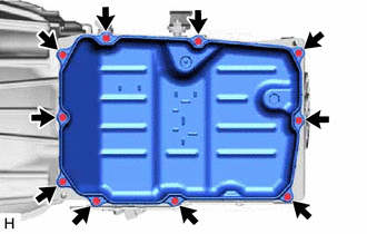
(b) Remove the 4 transmission oil cleaner magnets from the automatic transmission oil pan sub-assembly.
(c) Examine the particles in the automatic transmission oil pan sub-assembly.
(1) Collect any steel chips with the removed transmission oil cleaner magnets. Carefully inspect the foreign matter and particles in the automatic transmission oil pan sub-assembly and on the transmission oil cleaner magnets to anticipate the type of wear you will find in the automatic transmission assembly.
Steel (magnetic): bearing, gear and clutch plate wear
Brass (non-magnetic): bush wear
3. DISCONNECT TRANSMISSION WIRE
|
(a) Remove the 2 bolts and the 2 temperature sensor clamps, and disconnect the 2 temperature sensors. Text in Illustration
|
|

(b) Disconnect the 7 solenoid valve connectors and transmission wire from the transmission valve body assembly.
4. REMOVE TRANSMISSION INSULATOR RH (for 2GR-FKS)
|
(a) Remove the bolt and wire harness clamp bracket from the transmission insulator RH. |
|

(b) Remove the 2 bolts and transmission insulator RH from the automatic transmission assembly.
5. REMOVE TRANSMISSION INSULATOR RH (for 2TR-FE)
|
(a) Remove the 3 bolts and transmission insulator RH from the automatic transmission assembly. |
|

6. REMOVE TRANSMISSION WIRE
|
(a) Disconnect the transmission wire connector. HINT: Detach the claw, press down the lever, and disconnect the transmission wire connector. |
|

(b) Remove the bolt and pull out the transmission wire from the automatic transmission case sub-assembly.
|
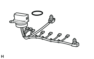
(c) Remove the O-ring from the connector of transmission wire. |
|
|
(d) Remove the 2 O-rings from the 2 temperature sensors. |
|

 Inspection
INSPECTION
PROCEDURE
1. INSPECT TRANSMISSION WIRE
(a) Measure the resistance according to the value(s) in the table below.
Text in Illustration
*a
...
 Installation
INSTALLATION
PROCEDURE
1. INSTALL TRANSMISSION WIRE
(a) Coat 2 new O-rings with ATF, and install them to the 2 temperature sensors.
(b) Coat a new O-ring with ATF, and install it to the transmissi ...
Other materials:
Sound of Portable Player cannot be Heard from Speakers or Sound is Low
PROCEDURE
1.
CHECK PORTABLE PLAYER SETTINGS
(a) Check the portable player settings.
(1) Check that the volume is not set to "0".
(2) Check that the mute is off.
(b) Check that the sound of the portable player can be heard from the speakers.
OK:
Sound ...
How To Proceed With Troubleshooting
CAUTION / NOTICE / HINT
HINT:
*: Use the Techstream.
PROCEDURE
1.
VEHICLE BROUGHT TO WORKSHOP
NEXT
2.
CUSTOMER PROBLEM ANALYSIS
Click here
(a) Confirm problem s ...
Rear Door(for Double Cab)
Components
COMPONENTS
ILLUSTRATION
ILLUSTRATION
ILLUSTRATION
ILLUSTRATION
ILLUSTRATION
Adjustment
ADJUSTMENT
CAUTION / NOTICE / HINT
HINT:
Use the same procedures for both the LH and RH sides.
The procedure described below is for the LH side.
Centering bolts ...
