Toyota Tacoma (2015-2018) Service Manual: Pattern Select Switch Power Mode Circuit
DESCRIPTION
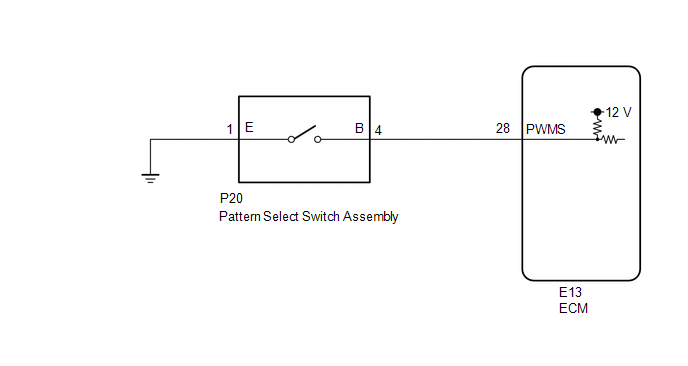
The ECM memory contains the programs for the normal and PWR shift patterns.
By following the programs corresponding to the signals from the pattern select switch assembly, park/neutral position switch and other various sensors, the ECM switches the shift solenoid valves on and off, and controls the transmission gear ratio.
WIRING DIAGRAM
PROCEDURE
|
1. |
INSPECT PATTERN SELECT SWITCH ASSEMBLY |
|
(a) Remove the pattern select switch assembly (See page
|
|
.gif) ).
).
(b) Measure the resistance according to the value(s) in the table below.
Standard Resistance:
|
Tester Connection |
Switch Condition |
Specified Condition |
|---|---|---|
|
1 (E) - 4 (B) |
Pattern select switch assembly pushed |
Below 1 Ω |
|
1 (E) - 4 (B) |
Pattern select switch assembly not pushed |
10 kΩ or higher |
|
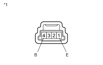
*1 |
Pattern Select Switch Assembly |
| NG | .gif) |
REPLACE PATTERN SELECT SWITCH ASSEMBLY |
|
.gif)
|
2. |
CHECK HARNESS AND CONNECTOR (PATTERN SELECT SWITCH ASSEMBLY - BODY GROUND) |
|
(a) Disconnect the pattern select switch assembly connector. |
|
(b) Measure the resistance according to the value(s) in the table below.
Standard Resistance:
|
Tester Connection |
Condition |
Specified Condition |
|---|---|---|
|
P20-1 (E) - Body ground |
Always |
Below 1 Ω |
|
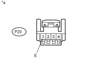
*a |
Front view of wire harness connector (to Pattern Select Switch Assembly) |
| NG | |
REPAIR OR REPLACE HARNESS OR CONNECTOR |
|
|
3. |
CHECK HARNESS AND CONNECTOR (PATTERN SELECT SWITCH ASSEMBLY - ECM) |
|
(a) Disconnect the ECM connector. |
|
(b) Measure the resistance according to the value(s) in the table below.
Standard Resistance:
|
Tester Connection |
Switch Condition |
Specified Condition |
|---|---|---|
|
E13-28 (PWMS) - Body ground |
Pattern select switch assembly pushed |
Below 1 Ω |
|
E13-28 (PWMS) - Body ground |
Pattern select switch assembly not pushed |
10 kΩ or higher |
|
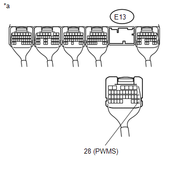
*a |
Rear view of wire harness connector (to ECM) |
| OK | |
PROCEED TO NEXT SUSPECTED AREA SHOWN IN PROBLEM SYMPTOMS TABLE |
| NG | |
REPAIR OR REPLACE HARNESS OR CONNECTOR |
 Torque Converter Clutch Pressure Control Solenoid Control Circuit Open (P275613)
DESCRIPTION
Refer to the system description for DTC P27567F (See page
).
DTC No.
DTC Detection Condition
Trouble Area
SAE
P275613
...

Other materials:
Brake Warning Light Remains ON
DESCRIPTION
The skid control ECU (brake actuator assembly) is connected to the combination
meter assembly via CAN communication.
If any of the following is detected, the brake warning light remains on:
The skid control ECU (brake actuator assembly) connector is disconnected
from the ...
On-vehicle Inspection
ON-VEHICLE INSPECTION
PROCEDURE
1. INSPECT REFRIGERANT PRESSURE WITH MANIFOLD GAUGE SET
(a) This is a method to specify trouble areas by using a manifold gauge set.
Read the manifold gauge pressure when the following conditions are established.
Test conditions:
Engine has been warmed u ...
Open in Outer Mirror Indicator(Slave) (C1AB5)
DESCRIPTION
This DTC is stored when the blind spot monitor sensor RH detects an open in the
blind spot monitor indicator RH.
DTC Code
DTC Detection Condition
Trouble Area
C1AB5
With the blind spot monitor main switch assembly (warning ...
