Toyota Tacoma (2015-2018) Service Manual: Parts Location
PARTS LOCATION
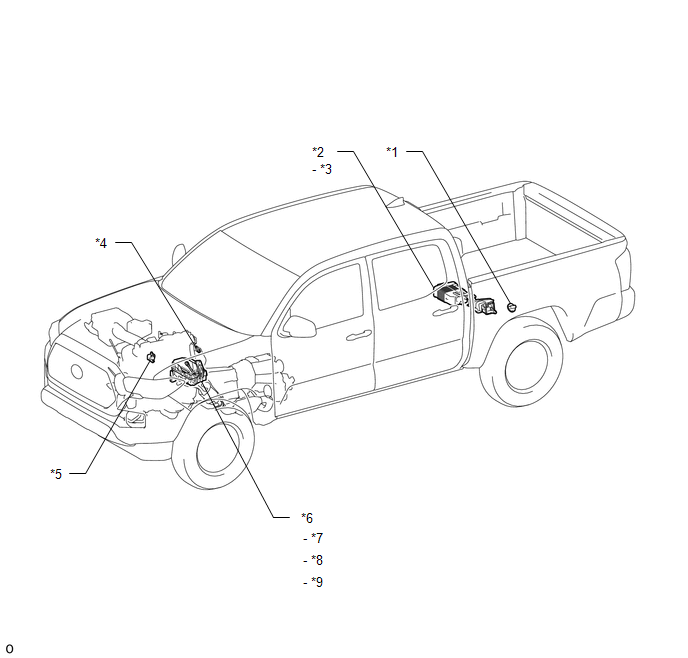
ILLUSTRATION
|
*1 |
FUEL TANK CAP ASSEMBLY |
*2 |
CHARCOAL CANISTER ASSEMBLY |
|
*3 |
CHARCOAL CANISTER LEAK DETECTION PUMP SUB-ASSEMBLY |
*4 |
PCV VALVE |
|
*5 |
PURGE VSV |
*6 |
ENGINE ROOM RELAY BLOCK |
|
*7 |
EFI-MAIN NO. 1 RELAY |
*8 |
EFI-MAIN FUSE |
|
*9 |
EFI NO. 3 FUSE |
- |
- |
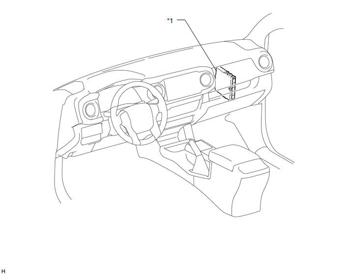
ILLUSTRATION
|
*1 |
ECM |
- |
- |
 On-vehicle Inspection
ON-VEHICLE INSPECTION
PROCEDURE
1. INSPECT FUEL CUT OPERATION
(a) Start the engine and warm it up.
(b) Increase the engine speed to at least 3500 rpm.
(c) Use a sound scope to check for fuel inje ...
 System Diagram
SYSTEM DIAGRAM
...
Other materials:
Refueling
Opening the fuel tank cap
Perform the following steps to open the fuel tank cap.
■ Before refueling the vehicle
Turn the engine switch off and ensure that all the doors and windows are closed.
■ Opening the fuel tank cap
Open the fuel filler door.
Turn the fuel tank cap slowly ...
Installation
INSTALLATION
PROCEDURE
1. INSTALL STEERING COLUMN ASSEMBLY
(a) Install the steering column assembly with the 2 nuts and bolt.
Torque:
21 N·m {214 kgf·cm, 15 ft·lbf}
(b) Connect each of the connectors to the steering column assembly.
(c) Connect the wire harness clamps to the steering colu ...
Parts Location
PARTS LOCATION
ILLUSTRATION
*A
for Hydraulic Brake Booster
*B
for Vacuum Brake Booster
*1
FORWARD RECOGNITION CAMERA
*2
MILLIMETER WAVE RADAR SENSOR ASSEMBLY
*3
HYDRAULIC BRA ...
