Toyota Tacoma (2015-2018) Service Manual: Parts Location
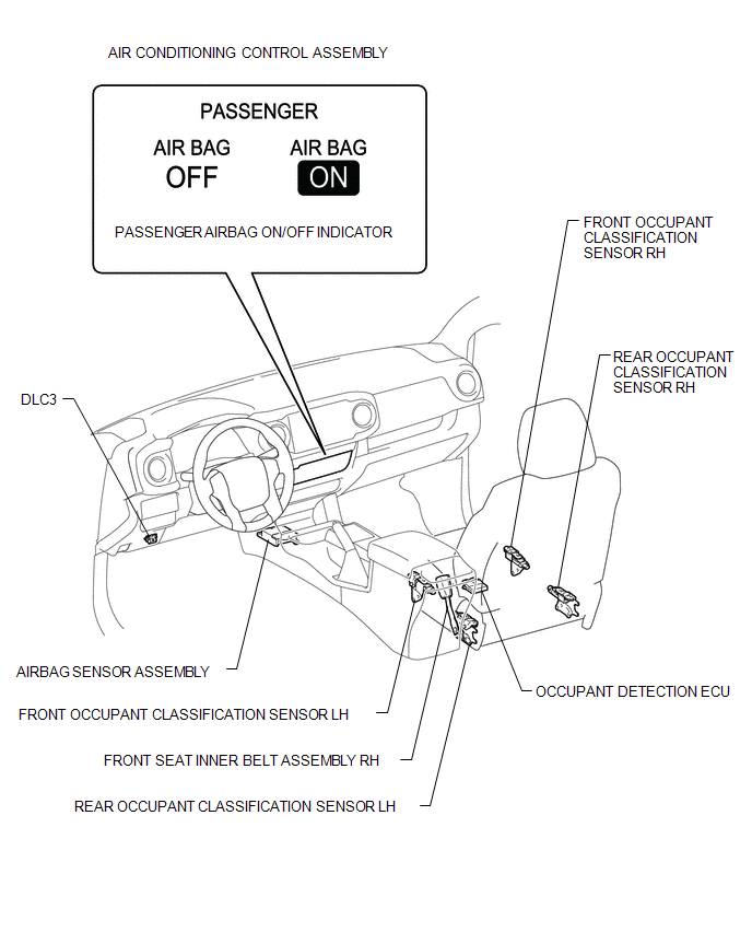
PARTS LOCATION
ILLUSTRATION

 Precaution
PRECAUTION
1. INSPECTION PROCEDURE FOR VEHICLE INVOLVED IN ACCIDENT
(a) Perform the zero point calibration and sensitivity check if any of the following
conditions apply.
The occupant dete ...
Other materials:
Transmission Fluid Temperature Sensor "B" Circuit Short to Ground (P274011)
DESCRIPTION
The No. 2 ATF temperature sensor is installed in the transmission valve body
assembly.
If the ECM detects an abnormally high ATF temperature near this sensor, it illuminates
the warning indicator.
HINT:
The temperature of ATF easily rises when towing, climbing hills, in
...
Disassembly
DISASSEMBLY
PROCEDURE
1. REMOVE TAIL GATE PROTECTOR
(See page )
2. REMOVE TAIL GATE SERVICE HOLE COVER
(a) Using a T30 "TORX" socket wrench, remove the 8 screws and tail gate
service hole cover.
3. REMOVE REAR TELEVISION CAMER ...
Short in Front Passenger Side Knee Airbag Squib Circuit (B1865/65-B1868/65)
DESCRIPTION
The passenger side knee airbag squib circuit consists of the airbag sensor assembly
and lower No. 2 instrument panel airbag assembly.
The airbag sensor assembly uses this circuit to deploy the airbag when deployment
conditions are met. These DTCs are stored when a malfunction is de ...
