Toyota Tacoma (2015-2018) Service Manual: Parts Location
PARTS LOCATION
ILLUSTRATION
|
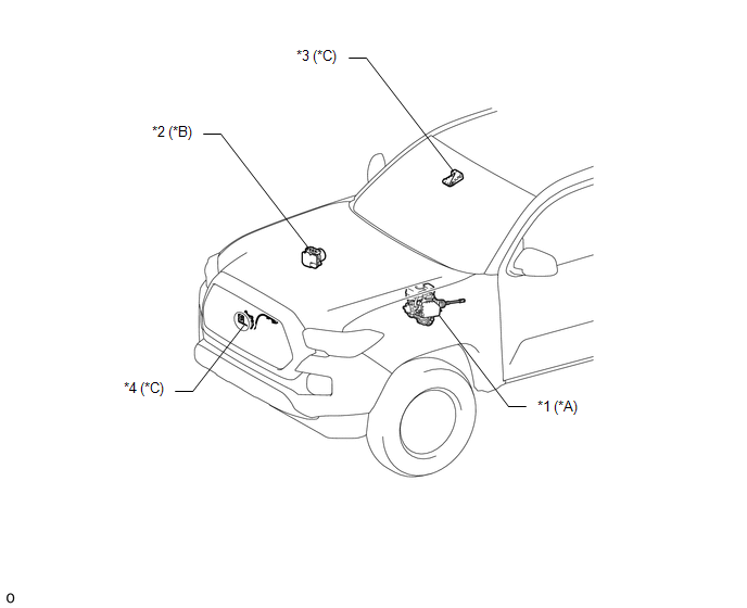
*A |
for Hydraulic Brake Booster |
*B |
for Vacuum Brake Booster |
|
*C |
w/ Toyota Safety Sense P |
- |
- |
|
*1 |
BRAKE BOOSTER ASSEMBLY (SKID CONTROL ECU) |
*2 |
BRAKE ACTUATOR ASSEMBLY (SKID CONTROL ECU) |
|
*3 |
FORWARD RECOGNITION CAMERA |
*4 |
MILLIMETER WAVE RADAR SENSOR ASSEMBLY |
ILLUSTRATION
|
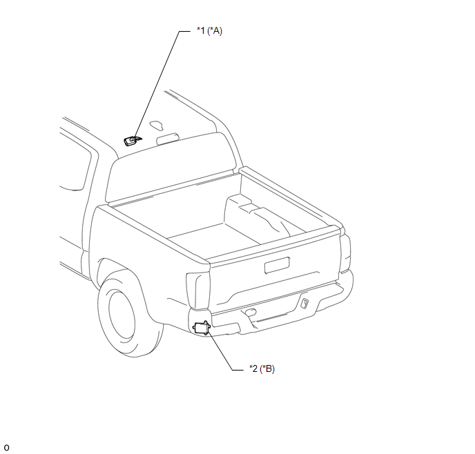
*A |
w/ Tire Pressure Warning System and Tire Inflation Pressure Display Function |
*B |
w/ Blind Spot Monitor System |
|
*1 |
DOOR CONTROL AND TIRE PRESSURE MONITORING SYSTEM RECEIVER ASSEMBLY |
*2 |
BLIND SPOT MONITOR SENSOR LH |
ILLUSTRATION
|
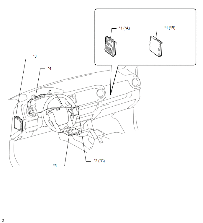
*A |
for 2GR-FKS |
*B |
for 2TR-FE |
|
*C |
w/ Intuitive Parking Assist System |
- |
- |
|
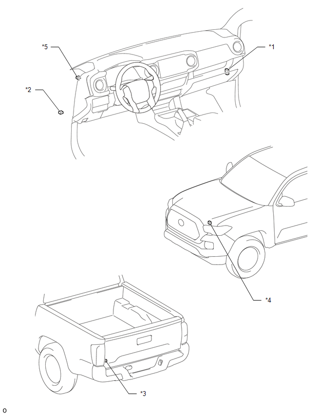
*1 |
ECM |
*2 |
CLEARANCE WARNING ECU ASSEMBLY |
|
*3 |
MAIN BODY ECU (MULTIPLEX NETWORK BODY ECU) |
*4 |
COMBINATION METER ASSEMBLY |
|
*5 |
AIRBAG SENSOR ASSEMBLY |
- |
- |
ILLUSTRATION
|
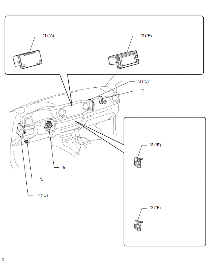
*A |
for Navigation Receiver Type |
*B |
for Radio and Display Type |
|
*C |
for 4WD |
*D |
w/ Smart Key System |
|
*E |
for Automatic Air Conditioning System |
*F |
for Manual Air Conditioning System |
|
*1 |
NAVIGATION RECEIVER ASSEMBLY |
*2 |
RADIO AND DISPLAY RECEIVER ASSEMBLY |
|
*3 |
4 WHEEL DRIVE CONTROL ECU |
*4 |
CERTIFICATION ECU (SMART KEY ECU ASSEMBLY) |
|
*5 |
DLC3 |
*6 |
SPIRAL CABLE WITH SENSOR SUB-ASSEMBLY |
|
*7 |
CENTRAL GATEWAY ECU (NETWORK GATEWAY ECU) |
*8 |
AIR CONDITIONING AMPLIFIER ASSEMBLY |
ILLUSTRATION
|
*1 |
NO. 1 CAN JUNCTION CONNECTOR |
*2 |
NO. 2 CAN JUNCTION CONNECTOR |
|
*3 |
NO. 4 CAN JUNCTION CONNECTOR |
*4 |
NO. 5 CAN JUNCTION CONNECTOR |
|
*5 |
NO. 6 CAN JUNCTION CONNECTOR |
- |
- |

 Precaution
PRECAUTION
1. EXPRESSIONS OF IGNITION SWITCH
HINT:
The type of ignition switch used on this model differs according to the specifications
of the vehicle. The expressions listed in the table below ...
Other materials:
Pressure Control Solenoid "D" Electrical (Shift Solenoid Valve SLT) (P2716)
DESCRIPTION
Refer to the system description for DTC P2714 (See page
).
DTC No.
DTC Detection Condition
Trouble Area
P2716
Open or short is detected in shift solenoid valve SLT circuit for 1 second
or more while driving (1 trip dete ...
Rear Occupant Classification Sensor RH Circuit Malfunction (B1783)
DESCRIPTION
The rear occupant classification sensor RH circuit consists of the occupant detection
ECU and the rear occupant classification sensor RH.
DTC B1783 is set when a malfunction is detected in the rear occupant classification
sensor RH circuit.
DTC No.
DTC Detect ...
Seat Position Airbag Sensor Circuit Malfunction (B1653/35)
DESCRIPTION
The seat position airbag sensor circuit consists of the airbag sensor assembly
and the seat position airbag sensor.
DTC B1653/35 is stored when a malfunction is detected in the seat position airbag
sensor assembly circuit.
DTC No.
DTC Detection Condition
...
