Toyota Tacoma (2015-2018) Service Manual: Operation Check
OPERATION CHECK
1. CHECK WINDOW LOCK FUNCTION
(a) Turn the ignition switch ON.
(b) Press the window lock switch of the power window regulator master switch assembly.
HINT:
The illumination (LED) built into the switch knob of each seat does not turn off.
(c) Check that the power window for each seat except the driver seat can no longer be operated.
(d) When the window lock switch is pressed again, check that the power window for each seat except the driver seat can be operated.
2. CHECK MANUAL UP / DOWN FUNCTION
(a) Check that the driver door power window operates as follows:
|
Condition |
Master Switch |
Switch Operation |
Power Window |
|---|---|---|---|
|
Ignition switch ON |
Driver door |
Pulled up |
UP (Closes) |
|
Pushed halfway down |
DOWN (Opens) |
(b) Check that the front passenger door window and rear power windows operate as follows:
|
Condition |
Regulator Switch |
Switch Operation |
Power Window |
|---|---|---|---|
|
Front passenger door |
Pulled up |
UP (Closes) |
|
Pushed down |
DOWN (Opens) |
||
|
Rear LH door*1 |
Pulled up |
UP (Closes) |
|
|
Pushed down |
DOWN (Opens) |
||
|
Rear RH door*1 |
Pulled up |
UP (Closes) |
|
|
Pushed down |
DOWN (Opens) |
- *1: for Double Cab
(c) Check that the power window (for back door power window)* operates as follows:
|
Condition |
Regulator Switch |
Switch Operation |
Power Window |
|---|---|---|---|
|
Ignition switch ON |
Back Door |
Pulled up |
Closes |
|
Pushed down |
Opens |
- *: w/ Back Door Power Window
3. CHECK AUTO DOWN FUNCTION
(a) Check that the driver door power window operates as follows:
|
Condition |
Master Switch |
Switch Operation |
Power Window |
|---|---|---|---|
|
Driver door |
Pushed down (One touch operation) |
AUTO DOWN (Opens) |
4. CHECK REMOTE MANUAL UP / DOWN FUNCTION
(a) Check that the front passenger door window and rear power windows operate as follows:
|
Condition |
Master Switch |
Switch Operation |
Power Window |
|---|---|---|---|
|
Ignition switch ON |
Front passenger door |
Pulled up |
UP (Closes) |
|
Pushed down |
DOWN (Opens) |
||
|
Rear LH door*1 |
Pulled up |
UP (Closes) |
|
|
Pushed down |
DOWN (Opens) |
||
|
Rear RH door*1 |
Pulled up |
UP (Closes) |
|
|
Pushed down |
DOWN (Opens) |
- *1: for Double Cab
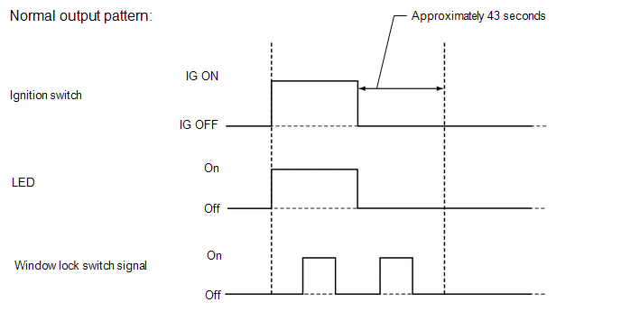
5. CHECK POWER WINDOW SWITCH LED ILLUMINATION
(a) When the ignition switch is turned from off to ON with the connectors connected, check that the illumination (LED) on the switch portion of the power window regulator switch assembly turns on.
 System Diagram
SYSTEM DIAGRAM
...
 Problem Symptoms Table
PROBLEM SYMPTOMS TABLE
HINT:
Use the table below to help determine the cause of problem symptoms.
If multiple suspected areas are listed, the potential causes of the symptoms
are lis ...
Other materials:
License Plate Light Assembly
Components
COMPONENTS
ILLUSTRATION
Removal
REMOVAL
CAUTION / NOTICE / HINT
HINT:
Use the same procedure for both the LH and RH sides.
The procedure described below is for the LH side.
PROCEDURE
1. REMOVE LICENSE PLATE LIGHT ASSEMBLY
(a) Disconnect the con ...
FCM Destination Information Unmatched (C1AA1)
DESCRIPTION
When the forward recognition camera is replaced with a new one, the new forward
recognition camera attempts to store country specification information received
from the main body ECU (multiplex network body ECU) and ECM. If the country specification
information stored in the forwa ...
Accumulator Low Pressure (C1256)
DESCRIPTION
The accumulator pressure sensor is connected to the skid control ECU in the master
cylinder solenoid.
DTC No.
DTC Detecting Condition
Trouble Areas
C1256
Fluid pressure inside the accumulator drops below the specification ...
