Toyota Tacoma (2015-2018) Service Manual: Open or Short Circuit in Back Camera Signal (C1622)
DESCRIPTION
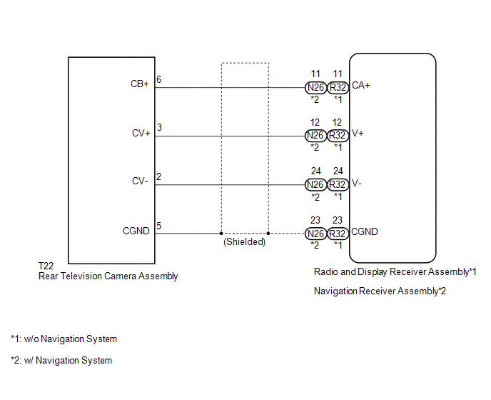
This DTC is stored if the radio and display receiver assembly*1 or navigation receiver assembly*2 judges as a result of its self check that the signals or signal lines between the radio and display receiver assembly*1 or navigation receiver assembly*2 and the rear television camera assembly are not normal.
|
DTC Code |
DTC Detection Condition |
Trouble Area |
|---|---|---|
|
C1622 |
Open or Short Circuit in rear television camera signal |
|
- *1: w/o Navigation System
- *2: w/ Navigation System
WIRING DIAGRAM
PROCEDURE
|
1. |
CHECK FOR DTC |
(a) Clear the DTCs (See page .gif) ).
).
(b) Check for DTCs (See page ).
|
Result |
Proceed to |
|---|---|
|
No DTC is output |
A |
|
DTC is output |
B |
| A | .gif) |
USE SIMULATION METHOD TO CHECK |
|
.gif)
|
2. |
CONFIRM MODEL |
(a) Choose the model to be inspected.
Result|
Result |
Proceed to |
|---|---|
|
w/o Navigation System |
A |
|
w/ Navigation System |
B |
| B | |
GO TO STEP 9 |
|
|
3. |
CHECK HARNESS AND CONNECTOR (RADIO AND DISPLAY RECEIVER ASSEMBLY - REAR TELEVISION CAMERA ASSEMBLY) |
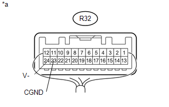
(a) Disconnect the R32 radio and display receiver assembly connector.
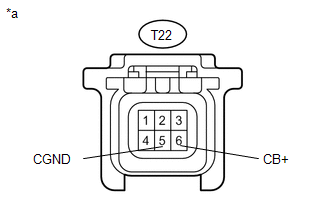
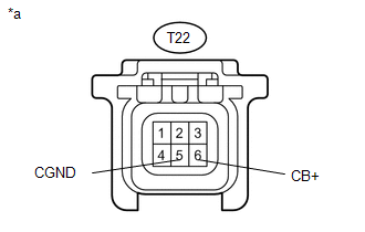
(b) Disconnect the T22 rear television camera assembly connector.
(c) Measure the resistance according to the value(s) in the table below.
Standard Resistance:
|
Tester Connection |
Condition |
Specified Condition |
|---|---|---|
|
R32-11 (CA+) - T22-6 (CB+) |
Always |
Below 1 Ω |
|
R32-12 (V+) - T22-3 (CV+) |
Always |
Below 1 Ω |
|
R32-23 (CGND) - T22-5 (CGND) |
Always |
Below 1 Ω |
|
R32-24 (V-) - T22-2 (CV-) |
Always |
Below 1 Ω |
|
R32-11 (CA+) - Body ground |
Always |
10 kΩ or higher |
|
R32-12 (V+) - Body ground |
Always |
10 kΩ or higher |
|
R32-23 (CGND) - Body ground |
Always |
10 kΩ or higher |
|
N26-24 (V-) - Body ground |
Always |
10 kΩ or higher |
| NG | |
REPAIR OR REPLACE HARNESS OR CONNECTOR |
|
|
4. |
CHECK RADIO AND DISPLAY RECEIVER ASSEMBLY |
|
(a) Measure the resistance according to the value(s) in the table below. Standard Resistance:
|
|
| NG | |
REPLACE RADIO AND DISPLAY RECEIVER ASSEMBLY |
|
|
5. |
CHECK RADIO AND DISPLAY RECEIVER ASSEMBLY |
|
(a) Disconnect the rear television camera assembly connector. |
|
(b) Measure the voltage according to the value(s) in the table below.
Standard Voltage:
|
Tester Connection |
Switch Condition |
Specified Condition |
|---|---|---|
|
T22-6 (CB+) - T22-5 (CGND) |
Ignition switch ACC |
5.5 to 7.05 V |
|
*a |
Front view of wire harness connector (to Rear Television Camera Assembly) |
| NG | |
REPLACE RADIO AND DISPLAY RECEIVER ASSEMBLY |
|
|
6. |
CHECK REAR TELEVISION CAMERA ASSEMBLY |
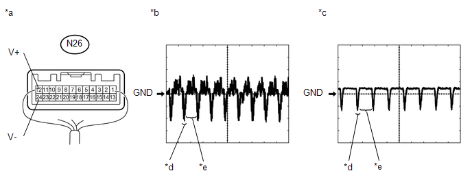
(a) Using an oscilloscope, check the waveform.
 Text in Illustration
|
*a |
Component with harness connected (Radio and Display Receiver Assembly) |
*b |
Waveform 1 |
|
*c |
Waveform 2 |
*d |
Synchronized Signal |
|
*e |
Video Waveform |
- |
- |
|
Item |
Content |
|---|---|
|
Tester Connection |
R32-12 (V+) - R32-24 (V-) |
|
Tool Setting |
0.2 V/DIV., 50 ÎĽs/DIV. |
|
Condition |
|
OK:
Waveform is as shown in illustration.
HINT:
The video waveform changes according to the image sent by the rear television camera assembly.
| OK | |
USE SIMULATION METHOD TO CHECK |
|
|
7. |
REPLACE REAR TELEVISION CAMERA ASSEMBLY |
(a) Replace the rear television camera assembly with a new or normally functioning
one (See page ).
|
|
8. |
CHECK FOR DTC |
(a) Clear the DTCs (See page ).
(b) Check for DTCs (See page ).
OK:
No DTCs are output.
| OK | |
END (REAR TELEVISION CAMERA ASSEMBLY WAS DEFECTIVE) |
| NG | |
REPLACE RADIO AND DISPLAY RECEIVER ASSEMBLY |
|
9. |
CHECK HARNESS AND CONNECTOR (NAVIGATION RECEIVER ASSEMBLY - REAR TELEVISIONCAMERA ASSEMBLY) |
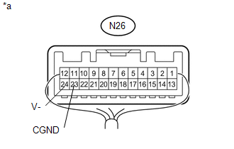
(a) Disconnect the N26 navigation receiver assembly connector.
(b) Disconnect the T22 rear television camera assembly connector.
(c) Measure the resistance according to the value(s) in the table below.
Standard Resistance:
|
Tester Connection |
Condition |
Specified Condition |
|---|---|---|
|
N26-11 (CA+) - T22-6 (CB+) |
Always |
Below 1 Ω |
|
N26-12 (V+) - T22-3 (CV+) |
Always |
Below 1 Ω |
|
N26-23 (CGND) - T22-5 (CGND) |
Always |
Below 1 Ω |
|
N26-24 (V-) - T22-2 (CV-) |
Always |
Below 1 Ω |
|
N26-11 (CA+) - Body ground |
Always |
10 kΩ or higher |
|
N26-12 (V+) - Body ground |
Always |
10 kΩ or higher |
|
N26-23 (CGND) - Body ground |
Always |
10 kΩ or higher |
|
N26-24 (V-) - Body ground |
Always |
10 kΩ or higher |
| NG | |
REPAIR OR REPLACE HARNESS OR CONNECTOR |
|
|
10. |
CHECK NAVIGATION RECEIVER ASSEMBLY |
|
(a) Measure the resistance according to the value(s) in the table below. Standard Resistance:
|
|
| NG | |
REPLACE NAVIGATION RECEIVER ASSEMBLY |
|
|
11. |
CHECK NAVIGATION RECEIVER ASSEMBLY |
|
(a) Disconnect the rear television camera assembly connector. |
|
(b) Measure the voltage according to the value(s) in the table below.
Standard Voltage:
|
Tester Connection |
Switch Condition |
Specified Condition |
|---|---|---|
|
T22-6 (CB+) - T22-5 (CGND) |
Ignition switch ACC |
5.5 to 7.05 V |
|
*a |
Front view of wire harness connector (to Rear Television Camera Assembly) |
| NG | |
REPLACE NAVIGATION RECEIVER ASSEMBLY |
|
|
12. |
CHECK REAR TELEVISION CAMERA ASSEMBLY |
(a) Using an oscilloscope, check the waveform.
 Text in Illustration
|
*a |
Component with harness connected (Navigation Receiver Assembly) |
*b |
Waveform 1 |
|
*c |
Waveform 2 |
*d |
Synchronized Signal |
|
*e |
Video Waveform |
- |
- |
|
Item |
Content |
|---|---|
|
Tester Connection |
N26-12 (V+) - N26-24 (V-) |
|
Tool Setting |
0.2 V/DIV., 50 ÎĽs/DIV. |
|
Condition |
|
OK:
Waveform is as shown in illustration.
HINT:
The video waveform changes according to the image sent by the rear television camera assembly.
| OK | |
USE SIMULATION METHOD TO CHECK |
|
|
13. |
REPLACE REAR TELEVISION CAMERA ASSEMBLY |
(a) Replace the rear television camera assembly with a new or normally functioning
one (See page ).
|
|
14. |
CHECK FOR DTC |
(a) Clear the DTCs (See page ).
(b) Check for DTCs (See page ).
OK:
No DTCs are output.
| OK | |
END (REAR TELEVISION CAMERA ASSEMBLY WAS DEFECTIVE) |
| NG | |
REPLACE NAVIGATION RECEIVER ASSEMBLY |
 Dtc Check / Clear
DTC CHECK / CLEAR
HINT:
Refer to Audio and Visual System (w/o Navigation System) (See page
).
Refer to Navigation System (w/ Navigation System) (See page
).
...
 Reverse Signal Circuit
DESCRIPTION
The radio and display receiver assembly*1 or navigation receiver assembly*2 receives
a reverse signal from the park/neutral position switch*3 or the back-up light switch
assembly*4.
...
Other materials:
Precaution
PRECAUTION
1. PRECAUTIONS WHEN USING TECHSTREAM
(a) When using the Techstream to troubleshoot the engine immobiliser system:
Connect the Techstream to the DLC3 while the ignition switch is off, and turn
a door courtesy light switch on and off at 1.5-second intervals until communication
betwee ...
USB port/AUX port
Connect an iPod, USB memory device or portable audio player to the USB port/AUX
port as indicated below. Select “iPod”, “USB” or “AUX” on the “Select Audio Source”
screen and the device can be operated via multimedia system.
Connecting using the USB port/AUX port
■ iPod
...
Satellite Radio Broadcast cannot be Received
CAUTION / NOTICE / HINT
NOTICE:
Some satellite radio broadcasts require payment. A contract must be
made between a satellite radio company and the user. If the contract expires,
it will not be possible to listen to the broadcast.
After replacing the stereo component tuner assem ...
