Toyota Tacoma (2015-2018) Service Manual: Open in Turn Signal Circuit (B1507,B1508)
DESCRIPTION
This DTC is stored when the combination meter assembly detects an open in a turn signal light circuit, a short in a turn signal light circuit, or a short in the hazard warning light circuit.
|
DTC No. |
DTC Detection Condition |
Trouble Area |
|---|---|---|
|
B1507 |
When IG voltage is 9.5 V or more and the following condition is detected:
|
|
|
B1508 |
When IG voltage is more than 7 V and the following condition is detected:
|
|
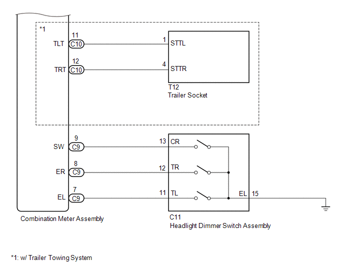
- *: except Trailer Towing System
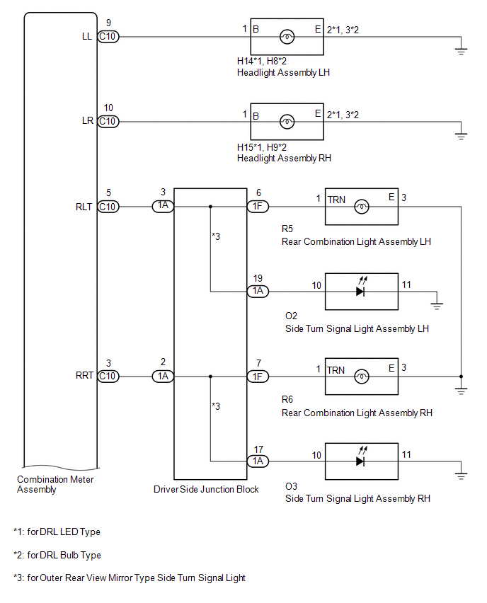
WIRING DIAGRAM
CAUTION / NOTICE / HINT
NOTICE:
Inspect the bulbs for circuits related to this system before performing the following inspection procedure.
PROCEDURE
|
1. |
INSPECT LIGHTS |
(a) Inspect the illumination of each turn signal light.
Result|
Result |
Proceed to |
|---|---|
|
Turn signal lights for one side do not illuminate (except Front Turn Signal Light) |
A |
|
Front turn signal light does not illuminate |
B |
|
Rear turn signal light does not illuminate |
C |
|
Side turn signal light does not illuminate (for Outer Rear View Mirror Type Side Turn Signal Light) |
D |
|
Trailer turn signal light does not illuminate (w/ Trail Towing System |
E |
| B | .gif) |
GO TO STEP 3 |
| C | |
GO TO STEP 4 |
| D | |
GO TO STEP 5 |
| E | |
GO TO STEP 6 |
|
.gif)
|
2. |
CHECK HARNESS AND CONNECTOR (COMBINATION METER ASSEMBLY - DRIVER SIDE JUNCTION BLOCK) |
(a) Disconnect the C10 combination meter assembly connector.
(b) Disconnect the 1A driver side junction block connector.
(c) Measure the resistance according to the value(s) in the table below.
Standard Resistance:
|
Tester Connection |
Condition |
Specified Condition |
|---|---|---|
|
C10-5 (RLT) - 1A-3 |
Always |
Below 1 Ω |
|
C10-5 (RLT) or 1A-3 - Body ground |
Always |
10 kΩ or higher |
|
C10-3 (RRT) - 1A-2 |
Always |
Below 1 Ω |
|
C10-3 (RRT) or 1A-2 - Body ground |
Always |
10 kΩ or higher |
|
Result |
Proceed to |
|---|---|
|
NG |
A |
|
OK |
B |
| A | |
REPAIR OR REPLACE HARNESS OR CONNECTOR |
| B | |
GO TO STEP 7 |
|
3. |
CHECK HARNESS AND CONNECTOR (HEADLIGHT ASSEMBLY - COMBINATION METER ASSEMBLY) |
(a) for DRL LED Type:
(1) Disconnect the H14 headlight assembly LH connectors.
(2) Disconnect the H15 headlight assembly RH connectors.
(3) Disconnect the C10 combination meter assembly connector.
(4) Measure the resistance according to the value(s) in the table below.
Standard Resistance:
|
Tester Connection |
Condition |
Specified Condition |
|---|---|---|
|
H14-1 (B) - C10-9 (LL) |
Always |
Below 1 Ω |
|
H14-2 (E) - Body ground |
Always |
Below 1 Ω |
|
H14-1 (B) or C10-9 (LL) - Body ground |
Always |
10 kΩ or higher |
|
H15-1 (B) - C10-10 (LR) |
Always |
Below 1 Ω |
|
H15-2 (E) - Body ground |
Always |
Below 1 Ω |
|
H15-1 (B) or C10-10 (LR) - Body ground |
Always |
10 kΩ or higher |
(b) for DRL Bulb Type:
(1) Disconnect the H8 headlight assembly LH connectors.
(2) Disconnect the H9 headlight assembly RH connectors.
(3) Disconnect the C10 combination meter assembly connector.
(4) Measure the resistance according to the value(s) in the table below.
Standard Resistance:
|
Tester Connection |
Condition |
Specified Condition |
|---|---|---|
|
H8-1 (B) - C10-9 (LL) |
Always |
Below 1 Ω |
|
H8-2 (E) - Body ground |
Always |
Below 1 Ω |
|
H8-1 (B) or C10-9 (LL) - Body ground |
Always |
10 kΩ or higher |
|
H9-1 (B) - C10-10 (LR) |
Always |
Below 1 Ω |
|
H9-2 (E) - Body ground |
Always |
Below 1 Ω |
|
H9-1 (B) or C10-10 (LR) - Body ground |
Always |
10 kΩ or higher |
| OK | |
REPLACE COMBINATION METER ASSEMBLY |
| NG | |
REPAIR OR REPLACE HARNESS OR CONNECTOR |
|
4. |
CHECK HARNESS AND CONNECTOR (REAR COMBINATION LIGHT ASSEMBLY - DRIVER SIDE JUNCTION BLOCK) |
(a) Disconnect the R5 rear combination light assembly LH connector.
(b) Disconnect the R6 rear combination light assembly RH connector.
(c) Disconnect the 1F driver side junction block connector.
(d) Measure the resistance according to the value(s) in the table below.
Standard Resistance:
|
Tester Connection |
Condition |
Specified Condition |
|---|---|---|
|
R5-1 - 1F-6 |
Always |
Below 1 Ω |
|
R5-3 - Body ground |
Always |
Below 1 Ω |
|
R5-1 or 1F-6 - Body ground |
Always |
10 kΩ or higher |
|
R6-1 - 1F-7 |
Always |
Below 1 Ω |
|
R6-1 - Body ground |
Always |
Below 1 Ω |
|
R6-1 or 1F-7 - Body ground |
Always |
10 kΩ or higher |
|
Result |
Proceed to |
|---|---|
|
NG |
A |
|
OK |
B |
| A | |
REPAIR OR REPLACE HARNESS OR CONNECTOR |
| B | |
GO TO STEP 7 |
|
5. |
CHECK HARNESS AND CONNECTOR (OUTER REAR VIEW MIRROR ASSEMBLY - DRIVER SIDE JUNCTION BLOCK) |
(a) Disconnect the O2 outer rear view mirror assembly LH connector.
(b) Disconnect the O3 outer rear view mirror assembly RH connector.
(c) Disconnect the 1A driver side junction block connector.
(d) Measure the resistance according to the value(s) in the table below.
Standard Resistance:
|
Tester Connection |
Condition |
Specified Condition |
|---|---|---|
|
O2-10 - 1A-19 |
Always |
Below 1 Ω |
|
O2-11 - Body ground |
Always |
Below 1 Ω |
|
O2-10 or 1A-19 - Body ground |
Always |
10 kΩ or higher |
|
O3-10 - 1A-17 |
Always |
Below 1 Ω |
|
O3-11 - Body ground |
Always |
Below 1 Ω |
|
O3-10 or 1A-17 - Body ground |
Always |
10 kΩ or higher |
|
Result |
Proceed to |
|---|---|
|
NG |
A |
|
OK |
B |
| A | |
REPAIR OR REPLACE HARNESS OR CONNECTOR |
| B | |
GO TO STEP 7 |
|
6. |
CHECK HARNESS AND CONNECTOR (COMBINATION METER ASSEMBLY - TRAILER SOCKET) |
(a) Disconnect the C10 combination meter assembly connector.
(b) Disconnect the T12 trailer socket connector.
(c) Measure the resistance according to the value(s) in the table below.
Standard Resistance:
|
Tester Connection |
Condition |
Specified Condition |
|---|---|---|
|
C10-11(TLT) - T12-1(STTL) |
Always |
Below 1 Ω |
|
C10-12(TRT) - T12-4(STTR) |
Always |
Below 1 Ω |
|
C10-11(TLT) or T12-1(STTL) - Body ground |
Always |
10 kΩ or higher |
|
C10-12(TRT) or T12-4(STTR) - Body ground |
Always |
10 kΩ or higher |
| OK | |
REPLACE COMBINATION METER ASSEMBLY |
| NG | |
REPAIR OR REPLACE HARNESS OR CONNECTOR |
|
7. |
INSPECT DRIVER SIDE JUNCTION BLOCK |
(a) Remove the main body ECU (multiplex network body ECU) from the instrument
panel junction block assembly (See page .gif) ).
).
 Text in Illustration
|
*a |
Component without harness connected (Driver Side Junction Block) |
- |
- |
(b) Measure the resistance according to the value(s) in the table below.
Standard Resistance:
|
Tester Connection |
Condition |
Specified Condition |
|---|---|---|
|
1A-3 - 1F-6 |
Always |
Below 1 Ω |
|
1A-3 - 1A-19*1 |
Always |
Below 1 Ω |
|
1A-2 - 1F-7 |
Always |
Below 1 Ω |
|
1A-2 - 1A-17*1 |
Always |
Below 1 Ω |
- *1: for Outer Rear View Mirror Type Side Turn Signal Light
| OK | |
REPLACE COMBINATION METER ASSEMBLY |
| NG | |
REPLACE DRIVER SIDE JUNCTION BLOCK |
 Fuel Sender Open Detected (B1500)
DESCRIPTION
This DTC is output when the combination meter assembly detects a fuel sender
gauge assembly malfunction.
DTC No.
DTC Detection Condition
Trouble Area
...
 Lost Communication with ECM / PCM "A" (U0100,U0129,U0142,U0151,U0163,U023A,U1104)
DESCRIPTION
The combination meter communicates with the ECM, skid control ECU, power steering
ECU, main body ECU (multiplex network body ECU), airbag sensor assembly, navigation
receiver assembly ...
Other materials:
System Diagram
SYSTEM DIAGRAM
Communication Table
Sender
Receiver
Signal
Line
Main Body ECU
(Multiplex Network Body ECU)
Clearance Warning ECU Assembly
Destination information signal
CAN Communication Line
...
Clutch Release Cylinder(for Rc62f)
Components
COMPONENTS
ILLUSTRATION
Disassembly
DISASSEMBLY
PROCEDURE
1. REMOVE CLUTCH RELEASE CYLINDER KIT
(a) Remove the boot from the cylinder body.
(b) Remove the push rod from the boot.
(c) Using compressed air, remove the piston together with the spring
from the cy ...
Voice Recognition Microphone Disconnected (B1579)
DESCRIPTION
The radio and display receiver assembly and telephone microphone assembly are
connected to each other using the microphone connection detection signal lines.
This DTC is stored when a microphone connection detection signal line is disconnected.
DTC Code
DTC Det ...
