Toyota Tacoma (2015-2018) Service Manual: On-vehicle Inspection
ON-VEHICLE INSPECTION
PROCEDURE
1. INSPECT RADIATOR CAP SUB-ASSEMBLY
CAUTION:
Do not remove the radiator cap sub-assembly while the engine and radiator assembly are still hot. Pressurized, hot engine coolant and steam may be released and cause serious burns.
(a) Measure the valve opening pressure.
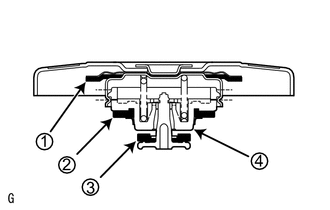
(1) If there are water stains or foreign matter on rubber packing 1, 2 or 3, clean it by using water and finger scouring.
(2) Check that rubber packing 1, 2 and 3 are not deformed, cracked or swollen.
(3) Check that rubber packing 3 and 4 are not stuck together.
(4) Apply engine coolant to rubber packing 2 and 3.
|
(5) When using the radiator cap tester, tilt it 30° or more. Text in Illustration
|
|
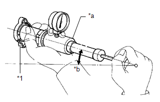
(6) Pump the radiator cap tester several times and check the maximum pressure.*1
Pumping speed:
1 pump per second
HINT:
*1: Even if the radiator cap sub-assembly cannot maintain the maximum pressure, it is not necessarily defective.
Standard Judgment Criterion:
|
Item |
Specified Condition |
|---|---|
|
Standard value (for brand-new cap) |
93 to 123 kPa (1.0 to 1.3 kgf/cm2, 14 to 18 psi) |
|
Minimum standard value (for used cap) |
79 kPa (0.8 kgf/cm2, 11 psi) |
If the maximum pressure is less than the minimum standard value, replace the radiator cap sub-assembly.
2. INSPECT FINS FOR BLOCKAGE
|
(a) If the fins are clogged, wash them with water or a steam cleaner and dry them with compressed air. NOTICE:
|
|
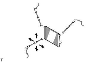
(b) Dry the fins with compressed air.
 Components
COMPONENTS
ILLUSTRATION
ILLUSTRATION
ILLUSTRATION
...
 Disassembly
DISASSEMBLY
PROCEDURE
1. REMOVE RADIATOR DRAIN COCK PLUG
(a) Remove the radiator drain cock plug from the radiator assembly.
(b) Remove the O-ring from the radiator drain cock plug.
2. REMOVE RAD ...
Other materials:
How To Proceed With Troubleshooting
CAUTION / NOTICE / HINT
HINT:
Use the following procedure to troubleshoot the air conditioning system.
*: Use the Techstream.
PROCEDURE
1.
VEHICLE BROUGHT TO WORKSHOP
NEXT
...
Dtc Check / Clear
DTC CHECK / CLEAR
1. CHECK FOR TRANSPONDER KEY ECU ASSEMBLY DTC
(a) Connect the Techstream to the DLC3.
(b) Turn the ignition switch to ON.
(c) Turn the Techstream on.
(d) Enter the following menus: Body Electrical / Immobiliser / Trouble Codes.
(e) Check the details of the DTC(s) (See page
...
System Description
SYSTEM DESCRIPTION
GENERAL
The cruise control main switch is used to turn the dynamic radar cruise control
system on and off, as well as operate 7 functions: SET, - (COAST), TAP-DOWN, RES
(RESUME), + (ACCEL), TAP-UP and CANCEL. The SET, TAP-DOWN, and - (COAST) functions,
and the RES (RESUME) ...
