Toyota Tacoma (2015-2018) Service Manual: No Response from Steering Lock ECU (B2786)
DESCRIPTION
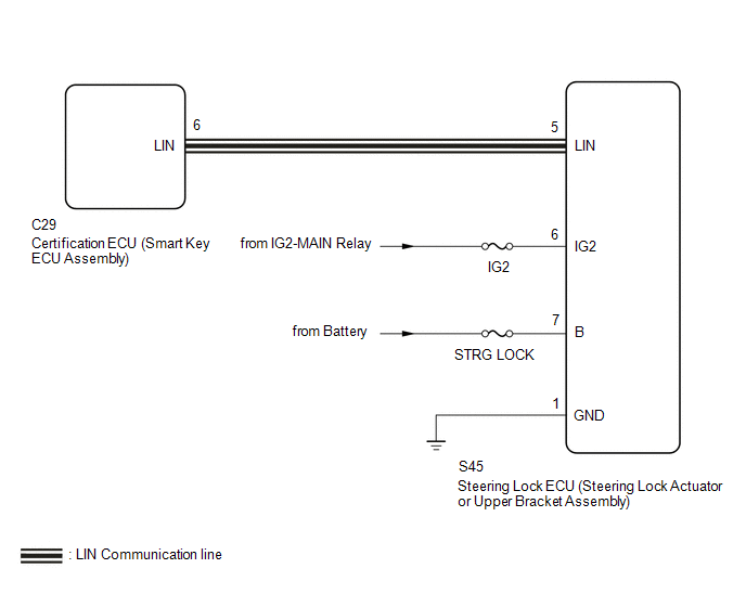
This DTC is stored when LIN communication between the certification ECU (smart key ECU assembly) and steering lock ECU (steering lock actuator or upper bracket assembly) stops for 10 seconds or more.
|
DTC No. |
DTC Detection Condition |
Trouble Area |
|---|---|---|
|
B2786 |
No communication between steering lock ECU (steering lock actuator or upper bracket assembly) and certification ECU (smart key ECU assembly) for 10 seconds or more. |
|
WIRING DIAGRAM
CAUTION / NOTICE / HINT
NOTICE:
- Inspect the fuses for circuits related to this system before performing the following inspection procedure.
- If the certification ECU (smart key ECU assembly) is replaced, register
the keys (See page
.gif) ).
). - If the steering lock ECU (steering lock actuator or upper bracket assembly)
is replaced, register the ECU code (See page
).
- When using the Techstream with the vehicle ignition switch off, connect the Techstream to the vehicle and turn a courtesy light switch on and off at intervals of 1.5 seconds or less until communication between the Techstream and the vehicle begins. Then select the vehicle type under manual mode and enter the following menus: Body Electrical / Smart Access. While using the Techstream, periodically turn a courtesy light switch on and off at intervals of 1.5 seconds or less to maintain communication between the Techstream and the vehicle.
PROCEDURE
|
1. |
CHECK DTC OUTPUT |
(a) Clear the DTCs (See page ).
(b) Recheck for DTCs.
|
Result |
Proceed to |
|---|---|
|
Only B2786 is output |
A |
|
DTC B2786 and B2785 are output simultaneously |
B |
HINT:
When DTC B2786 and B2785 are output simultaneously, perform troubleshooting for DTC B2785 first.
| B | .gif) |
GO TO DTC B2785 |
|
.gif)
|
2. |
CHECK HARNESS AND CONNECTOR (STEERING LOCK ECU (STEERING LOCK ACTUATOR OR UPPER BRACKET ASSEMBLY) - POWER SOURCE CIRCUIT) |
(a) Disconnect the S45 steering lock ECU (steering lock actuator or upper bracket assembly) connector.
(b) Measure the resistance and voltage according to the value(s) in the table below.
Standard Resistance:
|
Tester Connection |
Condition |
Specified Condition |
|---|---|---|
|
S45-1 (GND) - Body ground |
Always |
Below 1 Ω |
Standard Voltage:
|
Tester Connection |
Switch Condition |
Specified Condition |
|---|---|---|
|
S45-7 (B) - Body ground |
Always |
11 to 14 V |
|
S45-6 (IG2) - Body ground |
Ignition switch ON |
11 to 14 V |
| NG | |
REPAIR OR REPLACE HARNESS OR CONNECTOR |
|
|
3. |
CHECK HARNESS AND CONNECTOR (CERTIFICATION ECU (SMART KEY ECU ASSEMBLY) - STEERING LOCK ECU (STEERING LOCK ACTUATOR OR UPPER BRACKET ASSEMBLY)) |
(a) Disconnect the C29 certification ECU (smart key ECU assembly) connector.
(b) Disconnect the S45 steering lock ECU (steering lock actuator or upper bracket assembly) connector.
(c) Measure the resistance according to the value(s) in the table below.
Standard Resistance:
|
Tester Connection |
Condition |
Specified Condition |
|---|---|---|
|
C29-6 (LIN) - S45-5 (LIN) |
Always |
Below 1 Ω |
|
C29-6 (LIN) or S45-5 (LIN) - Body ground |
Always |
10 kΩ or higher |
| NG | |
REPAIR OR REPLACE HARNESS OR CONNECTOR |
|
|
4. |
REPLACE STEERING LOCK ECU (STEERING LOCK ACTUATOR OR UPPER BRACKET ASSEMBLY) |
(a) Replace the steering lock ECU (steering lock actuator or upper bracket assembly)
(See page ).
|
|
5. |
CHECK DTC OUTPUT |
(a) Clear the DTCs (See page ).
(b) Recheck for DTCs.
OK:
DTC B2786 is not output.
| OK | |
END (STEERING LOCK ECU (STEERING LOCK ACTUATOR OR UPPER BRACKET ASSEMBLY) WAS DEFECTIVE) |
| NG | |
REPLACE CERTIFICATION ECU (SMART KEY ECU ASSEMBLY) |
 Communication Malfunction between ECUs Connected by LIN (B2785)
DESCRIPTION
The certification ECU (smart key ECU assembly) monitors communication between
all the ECUs connected to the certification bus lines. When the certification ECU
(smart key ECU assembly ...
 Diagnostic Trouble Code Chart
DIAGNOSTIC TROUBLE CODE CHART
Main Body ECU (Multiplex Network Body ECU)
DTC Code
Detection Item
See page
B1206
P/W Master Switch Communi ...
Other materials:
Inspection
INSPECTION
PROCEDURE
1. INSPECT CENTER STOP LIGHT ASSEMBLY (for LED Type Stop Light)
(a) Check the illuminates.
(1) Apply battery voltage to the connector and check the light illumination
condition.
Text in Illustration
*a
Component without ...
On-vehicle Inspection
ON-VEHICLE INSPECTION
CAUTION / NOTICE / HINT
HINT:
Perform "Inspection After Repair" after replacing an ignition coil assembly or
spark plug (See page ).
PROCEDURE
1. PERFORM SPARK TEST
(a) Check for DTCs (See page ).
NOTICE:
If any DTC is output, perform the troubleshooting p ...
Clutch Switch
Components
COMPONENTS
ILLUSTRATION
Removal
REMOVAL
PROCEDURE
1. PRECAUTION
NOTICE:
After turning the engine switch off, waiting time may be required before disconnecting
the cable from the battery terminal. Therefore, make sure to read the disconnecting
the cable from the battery t ...
