Toyota Tacoma (2015-2018) Service Manual: Low Power Supply Voltage Malfunction (C1241)
DESCRIPTION
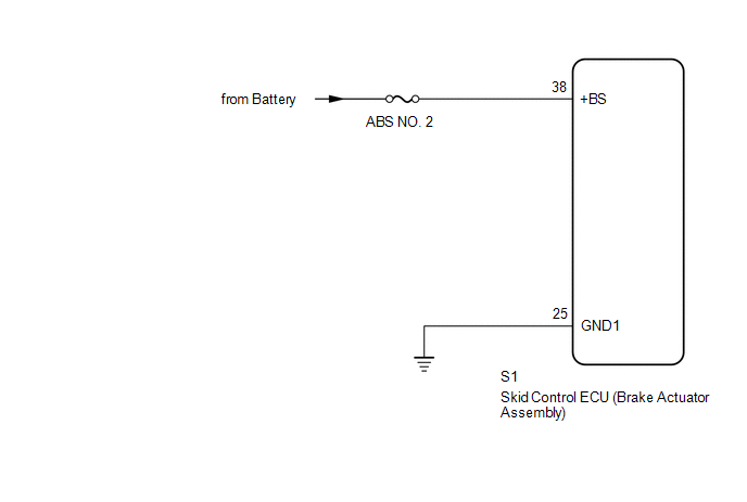
If a malfunction is detected in the power supply circuit, the skid control ECU (brake actuator assembly) stores this DTC and the fail-safe function prohibits ABS operation.
This DTC is stored when the +BS terminal voltage deviates from the DTC detection condition due to a malfunction in the power supply or charging circuit such as the battery or generator circuit, etc.
The DTC is canceled when the +BS terminal voltage returns to normal.
|
DTC No. |
Detection Item |
DTC Detection Condition |
Trouble Area |
|---|---|---|---|
|
C1241 |
Low Power Supply Voltage Malfunction |
Any of the following is detected:
|
|
HINT:
DTC will be output when conditions for any of the patterns in the table above are met.
WIRING DIAGRAM
CAUTION / NOTICE / HINT
NOTICE:
- When replacing the skid control ECU (brake actuator assembly), perform
zero point calibration and store system information (See page
.gif) ).
).
- Inspect the fuses for circuits related to this system before performing the following inspection procedure.
PROCEDURE
|
1. |
INSPECT BATTERY |
(a) Check the battery voltage.
Standard voltage:
11 to 14 V
| NG | .gif) |
CHECK OR REPLACE CHARGING SYSTEM OR BATTERY |
|
.gif)
|
2. |
CHECK TERMINAL VOLTAGE (+BS TERMINAL) |
(a) Turn the ignition switch off.
(b) Make sure that there is no looseness in the locking part and connecting part of the connectors.
|
(c) Disconnect the skid control ECU (brake actuator assembly) connector. |
|
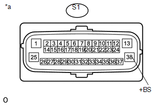
(d) Measure the voltage according to the value(s) in the table below.
Standard Voltage:
|
Tester Connection |
Condition |
Specified Condition |
|---|---|---|
|
S1-38 (+BS) - Body ground |
Always |
11 to 14 V |
|
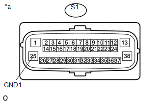
*a |
Front view of wire harness connector (to Skid Control ECU [Brake Actuator Assembly]) |
| NG | |
REPAIR OR REPLACE HARNESS OR CONNECTOR (+BS CIRCUIT) |
|
|
3. |
CHECK HARNESS AND CONNECTOR (GND1 TERMINAL) |
(a) Turn the ignition switch off.
|
(b) Measure the resistance according to the value(s) in the table below. Standard Resistance:
|
|
| NG | |
REPAIR OR REPLACE HARNESS OR CONNECTOR (GND1 CIRCUIT) |
|
|
4. |
RECONFIRM DTC |
(a) Reconnect the S1 skid control ECU (brake actuator assembly) connector.
(b) Clear the DTC (See page
).
(c) Turn the ignition switch off.
(d) Start the engine.
(e) Drive the vehicle at a speed of 20 km/h (12 mph) or more for 30 seconds or more.
(f) Check if the same DTC is recorded (See page
).
HINT:
If troubleshooting has been carried out according to the Problem Symptoms Table,
refer back to the table and proceed to the next step (See page
).
|
Result |
Proceed to |
|---|---|
|
DTC C1241 is not output |
A |
|
DTC C1241 is output |
B |
| A | |
USE SIMULATION METHOD TO CHECK |
| B | |
REPLACE BRAKE ACTUATOR ASSEMBLY |
 Diagnostic Trouble Code Chart
DIAGNOSTIC TROUBLE CODE CHART
VSC System
DTC Code
Detection Item
See page
C1201
Engine Control System Malfunction
...
 Vehicle Control History
VEHICLE CONTROL HISTORY
VEHICLE CONTROL HISTORY
(a) A part of the control history can be confirmed using the vehicle control
history.
Click here ...
Other materials:
Removal
REMOVAL
PROCEDURE
1. REMOVE FUEL TANK ASSEMBLY
Click here
2. DISCONNECT CHARCOAL CANISTER FUEL HOSE
(a) Loosen the hose clip and disconnect the charcoal canister fuel hose.
3. DISCONNECT FUEL TANK VENT HOSE
(a) Push the fuel tank vent hos ...
Hood
Release the lock from the inside of the vehicle to open the hood.
Pull the hood release lever.
The hood will pop up slightly.
Pull up the hood catch lever and lift the hood.
Hold the hood open by inserting the supporting rod into the slot.
CAUTION
■Pre-driving check
Check that the ...
Speed Sensor
Components
COMPONENTS
ILLUSTRATION
Removal
REMOVAL
PROCEDURE
1. REMOVE TRANSMISSION REVOLUTION SENSOR (NT)
(a) Disconnect the transmission revolution sensor (NT) connector.
(b) Remove the bolt and transmission revolution sensor (NT). ...
