Toyota Tacoma (2015-2018) Service Manual: Installation
INSTALLATION
PROCEDURE
1. INSTALL AIR CONDITIONING UNIT ASSEMBLY
(a) Temporary install the air conditioning unit assembly.
(b) Insert the bracket hook into the holes of the reinforcement bracket, and temporary install the instrument panel reinforcement assembly.
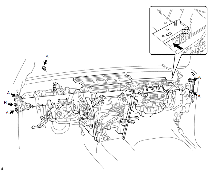
(c) Install the instrument panel reinforcement with the 6 bolts.
Torque:
Bolt A :
35 N·m {357 kgf·cm, 26 ft·lbf}
Bolt B :
31 N·m {311 kgf·cm, 22 ft·lbf}
(d) Install the 5 bolts in the order shown in the illustration.
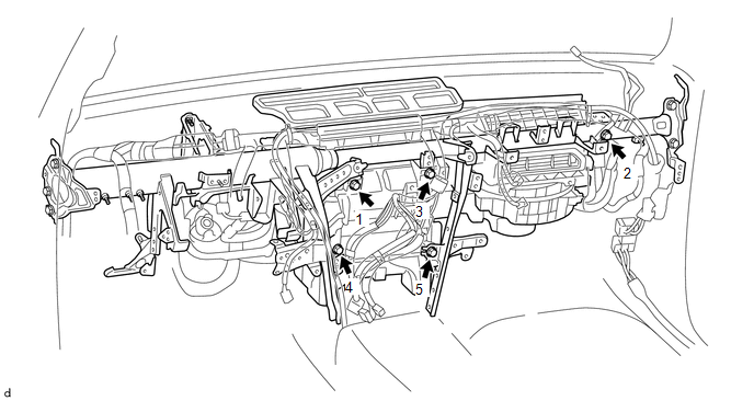
Torque:
5.0 N·m {51 kgf·cm, 44 in·lbf}
(e) Engage the 16 clamps.
(f) Connect the 2 ground wires with the 2 bolts.
(g) Connect the 2 airbag connectors.
(h) Engage the 4 clamps to install the instrument panel wire assembly.
(i) Connect the 5 connectors.
2. INSTALL AIR CONDITIONING AMPLIFIER ASSEMBLY
(a) Install the air conditioning amplifier assembly with the 2 bolts.
Torque:
7.0 N·m {71 kgf·cm, 62 in·lbf}
(b) Connect the 2 connectors.
3. INSTALL CLEARANCE WARNING ECU ASSEMBLY
Click here .gif)
4. INSTALL DRIVER SIDE JUNCTION BLOCK
(a) Install the driver side junction block with the 3 nuts.
Torque:
8.0 N·m {82 kgf·cm, 71 in·lbf}
5. INSTALL ECM (for 2TR-FE)
Click here
6. INSTALL ECM (for 2GR-FKS)
Click here
7. INSTALL NO. 1 INSTRUMENT PANEL BRACE MOUNTING BRACKET
(a) Install the No. 1 instrument panel brace mounting bracket with the bolt and nut.
Torque:
17 N·m {173 kgf·cm, 13 ft·lbf}
HINT:
Use the same procedure for both sides.
8. INSTALL AIR DUCT ASSEMBLY
(a) Engage the claw to install the air duct assembly.
(b) Install the bolt.
9. INSTALL HEATER AIR DUCT ASSEMBLY
(a) Install the heater air duct assembly with the 2 bolts.
10. INSTALL REAR NO. 1 AIR DUCT (for Double Cab)
(a) Engage the 2 claws to install the rear No. 1 air duct.
(b) Install the bolt.
11. INSTALL REAR AIR DUCT GUIDE RH (for Double Cab)
(a) Engage the 4 claws to install the rear air duct guide RH.
(b) Put the floor carpet back down.
12. INSTALL REAR NO. 2 AIR DUCT (for Double Cab)
(a) Engage the 2 claws to install the rear No. 2 air duct.
13. INSTALL REAR AIR DUCT GUIDE LH (for Double Cab)
(a) Engage the 4 claws to install the rear air duct guide LH.
(b) Put the floor carpet back down.
14. INSTALL INSTRUMENT PANEL SAFETY PAD
Click here
15. INSTALL STEERING COLUMN ASSEMBLY
Click here
16. INSTALL WINDSHIELD WIPER MOTOR AND LINK
Click here
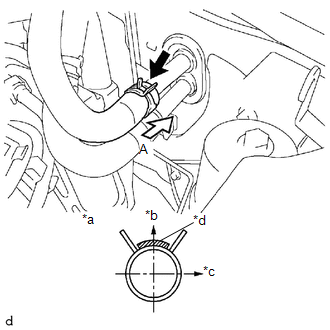
17. CONNECT WATER HOSE SUB-ASSEMBLY C (for 2TR-FE)
|
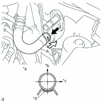
(a) Install the water hose sub-assembly C to the heater radiator assembly. Text in Illustration
HINT: Perform the installation with the hose clip and mark at the correct angle. |
|
18. CONNECT WATER HOSE SUB-ASSEMBLY C (for 2GR-FKS)
|
(a) Install the water hose sub-assembly C to the heater radiator assembly. Text in Illustration
HINT: Perform the installation with the hose clip and mark at the correct angle. |
|
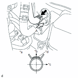
19. CONNECT WATER HOSE SUB-ASSEMBLY B (for 2TR-FE)
|
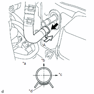
(a) Install the water hose sub-assembly B to the heater radiator assembly. Text in Illustration
HINT: Perform the installation with the hose clip and mark at the correct angle. |
|
20. INSTALL WATER HOSE SUB-ASSEMBLY B (for 2GR-FKS)
|
(a) Install the water hose sub-assembly B to the heater radiator assembly. Text in Illustration
HINT: Perform the installation with the hose clip and mark at the correct angle. |
|
21. INSTALL AIR CONDITIONING TUBE ASSEMBLY
(a) Apply compressor oil to 2 new O-rings and install them onto the hose.
Compressor oil:
PSD1 or equivalent
(b) Install the air conditioner tube assembly and piping clamp.
HINT:
Check that the claw of the piping clamp is correctly fitted.
(c) Engage the 2 clamps to install the air conditioner tube assembly.
(d) Install the bolt.
Torque:
7.5 N·m {76 kgf·cm, 66 in·lbf}
22. INSTALL SUCTION HOSE SUB-ASSEMBLY
(a) Apply compressor oil to 2 new O-rings and install them onto the pipe.
Compressor oil:
PSD1 or equivalent
(b) Install the air conditioner tube assembly and piping clamp.
HINT:
Check that the claw of the piping clamp is correctly fitted.
(c) Install the bracket with the 2 bolts.
Torque:
7.5 N·m {76 kgf·cm, 66 in·lbf}
23. CONNECT CABLE TO NEGATIVE BATTERY TERMINAL
Torque:
5.4 N·m {55 kgf·cm, 48 in·lbf}
NOTICE:
When disconnecting the cable, some systems need to be initialized after the cable is reconnected.
Click here
24. ADD ENGINE COOLANT (for 2TR-FE)
Click here
25. ADD ENGINE COOLANT (for 2GR-FKS)
Click here
26. CHECK FOR ENGINE COOLANT LEAK (for 2TR-FE)
Click here
27. CHECK FOR ENGINE COOLANT LEAK (for 2GR-FKS)
Click here
28. CHARGE AIR CONDITIONING SYSTEM WITH REFRIGERANT
Click here
29. WARM UP ENGINE
Click here
30. INSPECT FOR REFRIGERANT LEAK
Click here
31. PLACE FRONT WHEELS FACING STRAIGHT AHEAD
32. INSPECT SRS WARNING LIGHT
Click here
 Components
COMPONENTS
ILLUSTRATION
ILLUSTRATION
ILLUSTRATION
ILLUSTRATION
ILLUSTRATION
ILLUSTRATION
ILLUSTRATION
...
 Air Inlet Control Servo Motor
Inspection
INSPECTION
PROCEDURE
1. INSPECT AIR INLET CONTROL SERVO MOTOR
(a) Inspect the servo motor operation.
(1) Connect the positive (+) lead from the battery to terminal 1 (FR ...
Other materials:
Clearance Warning ECU Power Source Circuit
DESCRIPTION
This circuit provides power to operate the clearance warning ECU assembly.
WIRING DIAGRAM
CAUTION / NOTICE / HINT
NOTICE:
Inspect the fuse for circuits related to this system before performing the following
inspection procedure.
PROCEDURE
1.
CHECK HARNES ...
Steering Pad Switch Circuit
DESCRIPTION
This circuit sends an operation signal from the steering pad switch assembly
to the navigation receiver assembly.
If there is an open in the circuit, the audio system cannot be operated using
the steering pad switch assembly.
If there is a short in the circuit, the same condition ...
Removal
REMOVAL
CAUTION / NOTICE / HINT
NOTICE:
Release the vacuum from booster by depressing the brake pedal several times.
Then remove the brake master cylinder from brake booster.
PROCEDURE
1. PRECAUTION
NOTICE:
After turning the ignition switch off, waiting time may be required before disconnect ...
