Toyota Tacoma (2015-2018) Service Manual: Installation
INSTALLATION
PROCEDURE
1. TEMPORARILY TIGHTEN FRONT SUSPENSION LOWER ARM
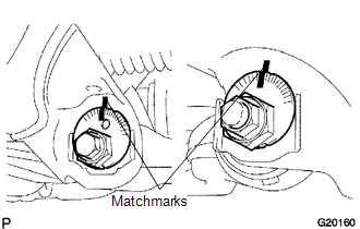
(a) Align the matchmarks on the camber adjust cam No. 2 and toe adjust cam. Temporarily tighten the bolt and the nut.
(b) Install the front lower ball joint attachment, a new nut and a new cotter pin.
Torque:
140 N·m {1428 kgf·cm, 103 ft·lbf}
|
(c) Install the front lower ball joint attachment with the 2 bolts. Torque: 160 N·m {1632 kgf·cm, 118 ft·lbf} |
|
.png)
2. TEMPORARILY TIGHTEN FRONT SHOCK ABSORBER WITH COIL SPRING
.png)
(a) Install the front shock absorber with coil spring, bolt and washer, and temporarily tighten the nut.
3. INSTALL FRONT WHEEL
Torque:
113 N·m {1152 kgf·cm, 83 ft·lbf}
4. STABILIZE FRONT SUSPENSION
(a) Lower the vehicle.
(b) Bounce the vehicle up and down several times to stabilize the suspension.
5. FULLY TIGHTEN FRONT SUSPENSION LOWER ARM
|
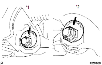
(a) Fully tighten the bolt and nut. Text in Illustration
Torque: for Front Side : 183 N·m {1866 kgf·cm, 135 ft·lbf} for Rear Side : 188 N·m {1917 kgf·cm, 139 ft·lbf} |
|
6. FULLY TIGHTEN FRONT SHOCK ABSORBER WITH COIL SPRING
(a) Fully tighten the nut.
Torque:
83 N·m {846 kgf·cm, 61 ft·lbf}
7. INSPECT AND ADJUST FRONT WHEEL ALIGNMENT
(See page .gif) )
)
 Inspection
INSPECTION
PROCEDURE
1. INSPECT FRONT SUSPENSION LOWER ARM
(a) Flip the ball joint stud back and forth 5 times, as shown in the illustration,
before installing the nut.
(b) Using a torque wren ...
 Reassembly
REASSEMBLY
PROCEDURE
1. INSTALL FRONT LOWER ARM BUSH NO. 1
(a) Install a new lower arm bush using SST, a press and steel plate.
SST: 09631-12090
SST: 09631-32020
NOTICE:
Push the lower arm bu ...
Other materials:
Dtc Check / Clear
DTC CHECK / CLEAR
NOTICE:
The steering lock ECU (steering lock actuator or UPR bracket assembly)
does not store history DTCs. If any DTCs are output, confirm and record
them as soon as possible. Do not turn the engine switch off or clear the
DTCs until the DTCs are confirmed an ...
Brake Warning Light does not Come ON
DESCRIPTION
Refer to Brake Warning Light Remains ON (See page
).
WIRING DIAGRAM
Refer to Brake Warning Light Remains ON (See page
).
CAUTION / NOTICE / HINT
NOTICE:
When replacing the skid control ECU (master cylinder solenoid), perform
calibration (See page
).
Inspect ...
Installation
INSTALLATION
PROCEDURE
1. INSTALL BRAKE ACTUATOR BRACKET ASSEMBLY
(a) Install the actuator bracket with the 3 bolts in the sequence shown
in the illustration.
Torque:
5.4 N·m {55 kgf·cm, 48 in·lbf}
2. INSTALL BRAKE ACTUATOR ...
