Toyota Tacoma (2015-2018) Service Manual: Installation
INSTALLATION
PROCEDURE
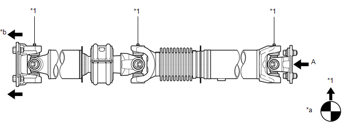
1. INSPECT PROPELLER SHAFT WITH CENTER BEARING ASSEMBLY (with Grease Fitting)
 Text in Illustration
|
*1 |
Grease Fitting |
- |
- |
|
*a |
View A |
*b |
Front Side |
HINT:
When replacing the spider bearing, make sure that the grease fitting assembly hole is facing in the direction shown in the illustration.
2. INSTALL PROPELLER SHAFT WITH CENTER BEARING ASSEMBLY
|
(a) Align the matchmarks on the propeller shaft flange yoke and transfer flange. Text in Illustration
|
|
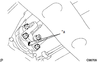
(b) Install the propeller shaft with the 4 nuts and 4 washers.
Torque:
88 N·m {899 kgf·cm, 65 ft·lbf}
|
(c) Align the matchmarks on the propeller shaft flange yoke and differential flange. Text in Illustration
|
|
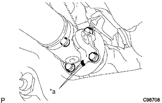
(d) for Differential Type BD20:
(1) Install the propeller shaft with the 4 bolts, 4 washers and 4 nuts.
Torque:
88 N·m {899 kgf·cm, 65 ft·lbf}
(e) for Differential Type BD22:
(1) Install the propeller shaft with the 4 washers and 4 nuts.
Torque:
88 N·m {899 kgf·cm, 65 ft·lbf}
|
(f) Provisionally install the center support bearing with 2 mounting bolts. Text in Illustration
HINT: Make sure the bearing is installed with the drain hole facing downwards. |
|
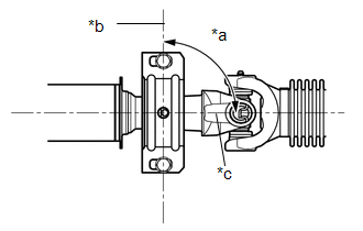
(g) Tighten the 2 bolts.
Torque:
36 N·m {369 kgf·cm, 27 ft·lbf}
 Inspection
INSPECTION
PROCEDURE
1. INSPECT PROPELLER SHAFT WITH CENTER BEARING ASSEMBLY
(a) Using a dial indicator, check the propeller shaft runout.
Maximum runout:
0.6 mm (0.0236 in.)
If the shaft run ...
 Reassembly
REASSEMBLY
PROCEDURE
1. INSPECT CENTER NO. 2 SUPPORT BEARING ASSEMBLY
(a) Turn the center bearing by hand, check that it turns smoothly without catching
and that there are no cracks or damage.
...
Other materials:
Inspection
INSPECTION
PROCEDURE
1. INSPECT OIL CLEARANCE
(a) Using a micrometer and caliper gauge, measure the oil seal clearance.
Text in Illustration
*1
Pulley Shaft
*2
Front Vane Pump Housing
...
Diagnostic Trouble Code Chart
DIAGNOSTIC TROUBLE CODE CHART
Differential System (w/ Differential Lock)
DTC Code
Detection Item
See page
P163B
4WD ECU Malfunction
P17BB
Rear Differential Lock Position SW Stuck OFF
...
Blind Spot Monitor Master Module Beam Axis Inspection Incomplete (C1ABB)
DESCRIPTION
This DTC is stored when a beam axis inspection has not been performed for the
blind spot monitor sensor LH.
HINT:
This DTC is always stored after replacing a blind spot monitor sensor. The purpose
of this DTC is to ensure that beam axis inspection is performed. Completing the
be ...
