Toyota Tacoma (2015-2018) Service Manual: Inspection
INSPECTION
PROCEDURE
1. INSPECT PROPELLER SHAFT WITH CENTER BEARING ASSEMBLY
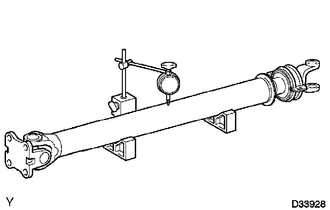
(a) Using a dial indicator, check the propeller shaft runout.
Maximum runout:
0.6 mm (0.0236 in.)
If the shaft runout is greater than the maximum, replace the shaft.
2. INSPECT PROPELLER SHAFT
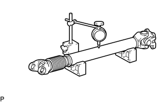
(a) Using a dial indicator, check the propeller shaft runout.
Maximum runout:
0.6 mm (0.0236 in.)
If the shaft runout is greater than the maximum, replace the shaft.
 Disassembly
DISASSEMBLY
PROCEDURE
1. REMOVE REAR PROPELLER SHAFT BOOT CLAMP
(a) Place matchmarks on the propeller shaft and sleeve yoke.
Text in Illustration
*1
...
 Installation
INSTALLATION
PROCEDURE
1. INSPECT PROPELLER SHAFT WITH CENTER BEARING ASSEMBLY (with Grease Fitting)
Text in Illustration
*1
Grease Fitting
-
-
...
Other materials:
PTC Heater Circuit
DESCRIPTION
PTC HTR heater relays are closed in accordance with signals from the air conditioning
amplifier assembly and power is supplied to the quick heater assembly installed
on the radiator heater unit.
WIRING DIAGRAM
CAUTION / NOTICE / HINT
NOTICE:
Inspect the fuses for circuits rela ...
Diagnostic Trouble Code Chart
DIAGNOSTIC TROUBLE CODE CHART
Air Conditioning System
DTC Code
Detection Item
Memory
See page
B1412
Ambient Temperature Sensor Circuit
Memorized
(4 seconds or more)
B1413
...
How To Proceed With Troubleshooting
CAUTION / NOTICE / HINT
HINT:
Use these procedures to troubleshoot the key reminder warning system.
*: Use the Techstream.
PROCEDURE
1.
VEHICLE BROUGHT TO WORKSHOP
NEXT
...
