Toyota Tacoma (2015-2018) Service Manual: Installation
INSTALLATION
PROCEDURE
1. INSPECT FRONT PROPELLER SHAFT ASSEMBLY (with Grease Fitting)
HINT:
When replacing the spider bearing, make sure that the grease fitting assembly hole is facing in the direction shown in the illustration.
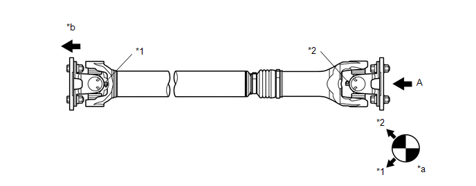 Text in Illustration
|
*1 |
No. 1 Grease Fitting |
*2 |
No. 2 Grease Fitting |
|
*a |
View A |
*b |
Front Side |
2. INSTALL FRONT PROPELLER SHAFT ASSEMBLY
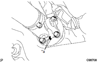
(a) Align the matchmarks on the propeller shaft flange and differential flange.
Text in Illustration|
*a |
Matchmark |
(b) Install the propeller shaft with the 4 bolts, 4 nuts and 4 washers.
Torque:
88 N·m {899 kgf·cm, 65 ft·lbf}
|
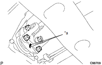
(c) Align the matchmarks on the propeller shaft flange and transfer flange. Text in Illustration
|
|
(d) Install the propeller shaft with the 4 nuts and 4 washers.
Torque:
88 N·m {899 kgf·cm, 65 ft·lbf}
3. INSTALL PROPELLER SHAFT HEAT INSULATOR BRACKET SUB-ASSEMBLY
.png)
(a) Install the propeller shaft heat insulator bracket with the 2 bolts.
Torque:
16 N·m {160 kgf·cm, 12 ft·lbf}
4. INSTALL FRONT NO. 2 EXHAUST PIPE ASSEMBLY (for 2GR-FKS)
.gif)
 Reassembly
REASSEMBLY
PROCEDURE
1. INSTALL FRONT PROPELLER SHAFT UNIVERSAL JOINT SPIDER BEARING
(a) Apply MP grease to a new spider and spider bearing.
(b) Fit the spider into the flange yoke.
...

Other materials:
Satellite Radio Broadcast cannot be Selected or After Selecting Broadcast, Broadcast
cannot be Added into Memory
CAUTION / NOTICE / HINT
NOTICE:
Some satellite radio broadcasts require payment. A contract must be made between
a satellite radio company and the user. If the contract expires, it will not be
possible to listen to the broadcast.
PROCEDURE
1.
CHECK NAVIGATION RECEIVER ...
Components
COMPONENTS
ILLUSTRATION
*A
w/o Navigation System
*B
w/ Navigation System
*C
for Double Cab
*D
for Acces Cab
*E
for 4WD
-
-
*1
...
Data List / Active Test
DATA LIST / ACTIVE TEST
1. DATA LIST
HINT:
Using the Techstream to read the Data List allows the values or states of switches,
sensors, actuators and other items to be read without removing any parts. This non-intrusive
inspection can be very useful because intermittent conditions or signals ...
