Toyota Tacoma (2015-2018) Service Manual: Inner Rear View Mirror
Components
COMPONENTS
ILLUSTRATION
ILLUSTRATION
Calibration
CALIBRATION
1. SELECT COMPASS DISPLAY MODE
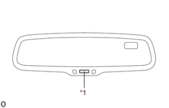
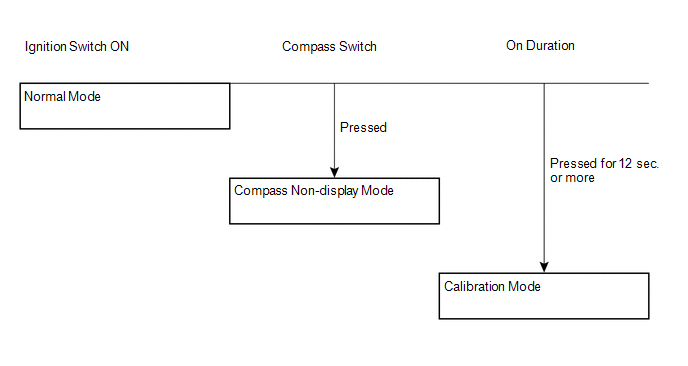
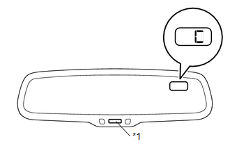
(a) The compass switch allows you to select the Display or Non-display mode of the compass.
|
*1 |
Compass Switch / EC Control Switch |
2. PERFORM CALIBRATION
(a) As each vehicle has its own magnetic field, calibration should be performed for each individual vehicle. This compass function is used when storing the record of the vehicle's magnetic field.
3. WHEN COMPASS IS MAGNETIZED
(a) A compass could be magnetized during shipping by vessels or freight cars. Therefore, make sure to perform calibration and ensure that calibration is performed properly before delivery. If this cannot be done (cannot be completed in spite of driving around several times), it may be caused by magnetization. Demagnetize the vehicle using a demagnetizer and perform calibration again.
4. SET COMPASS
5. CALIBRATION SETTING MODE
(a) Pressing the compass switch for 12 seconds or more in the normal mode will activate the calibration setting mode. "C" is displayed on the compass display.
|
*1 |
Compass Switch |
(b) Drive the vehicle at a slow speed of 8 km/h (5 mph) or less in a circular direction.
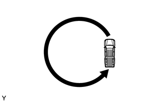
(c) Driving in a circle 1 to 3 times will display the azimuthal direction on the display, completing the calibration.
HINT:
After the calibration is completed, it is not necessary to perform the above procedures unless the magnetic field strength is drastically changed. If this happens, the azimuthal display will be changed to "C".
Inspection
INSPECTION
PROCEDURE
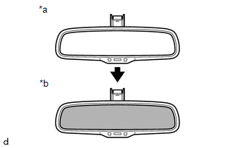
1. INSPECT INNER REAR VIEW MIRROR ASSEMBLY (w/ EC Mirror)
(a) Check operation of the electrochromic inner rear view mirror.
|
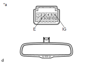
(1) Connect the positive (+) lead of the battery to terminal 6 (IG) and negative (-) lead to terminal 3 (E). Text in Illustration
|
|
|
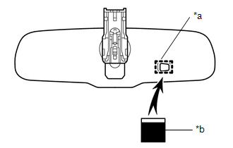
(2) Attach black-colored tape to the forward sensor to prevent it from sensing light. Text in Illustration
|
|
|
(3) Shine an electric light on the mirror. Check that the mirror surface changes from bright to dark. Text in Illustration
HINT: When the environment is very bright, the antiglare operation may occur immediately after the tape is applied. If the result is not as specified, replace the mirror assembly. |
|
Installation
INSTALLATION
PROCEDURE
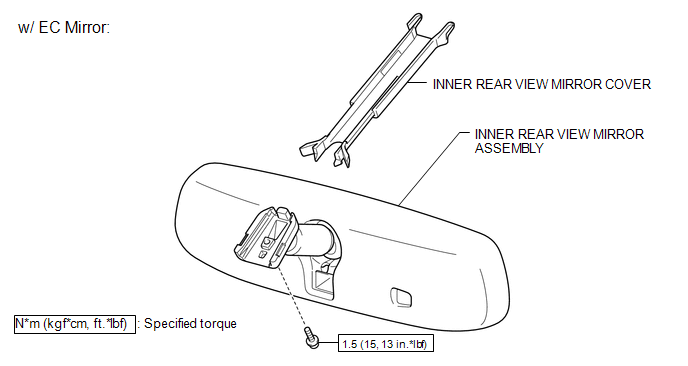
1. INSTALL INNER REAR VIEW MIRROR ASSEMBLY (w/ EC Mirror)
(a) Using a T20 "TORX" socket wrench, install the inner rear view mirror assembly with the screw.
Torque:
1.5 N·m {15 kgf·cm, 13 in·lbf}
(b) Connect the connector.
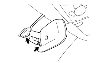
2. INSTALL INNER REAR VIEW MIRROR COVER (w/ EC Mirror)
|
(a) Slide the inner rear view mirror cover in the direction indicated by the arrow in the illustration to engage the 2 claws to the roof headlining to install the inner rear view mirror cover. |
|

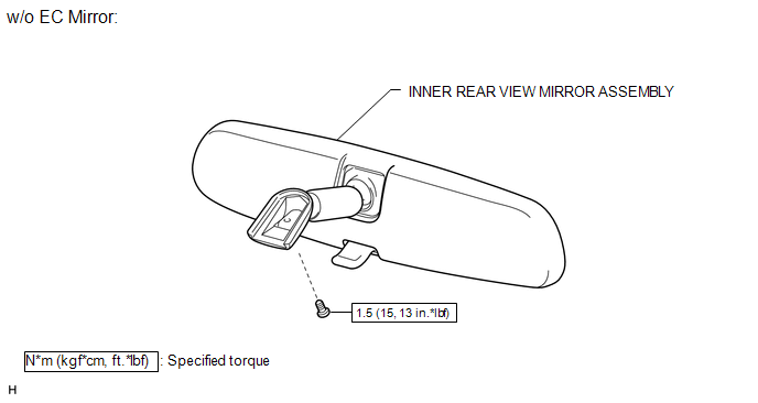
3. INSTALL INNER REAR VIEW MIRROR ASSEMBLY (w/o EC Mirror)
(a) Using a T20 "TORX" socket wrench, install the inner rear view mirror assembly with the screw.
Torque:
1.5 N·m {15 kgf·cm, 13 in·lbf}
Removal
REMOVAL
PROCEDURE
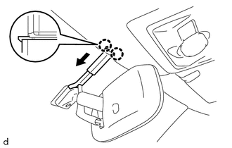
1. REMOVE INNER REAR VIEW MIRROR COVER (w/ EC Mirror)
|
(a) Slide the inner rear view mirror cover in the direction indicated by the arrow in the illustration to disengage the 2 claws from the roof headlining to remove the inner rear view mirror cover. |
|
2. REMOVE INNER REAR VIEW MIRROR ASSEMBLY (w/ EC Mirror)
|
(a) Disconnect the connector. |
|
(b) Using a T20 "TORX" socket wrench, remove the screw and inner rear view mirror assembly.
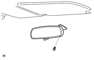
3. REMOVE INNER REAR VIEW MIRROR ASSEMBLY (w/o EC Mirror)
|
(a) Using a T20 "TORX" socket wrench, remove the screw and inner rear view mirror assembly. |
|
 Mirror
...
 Outer Mirror Switch
Inspection
INSPECTION
PROCEDURE
1. INSPECT OUTER MIRROR SWITCH ASSEMBLY
(a) Check the mirror select switch and mirror surface adjust switch.
(1) Turn the mirror select switch to the ...
Other materials:
Diagnostic Trouble Code Chart
DIAGNOSTIC TROUBLE CODE CHART
HINT:
If a trouble code is displayed during the DTC check, inspect the trouble areas
listed for that code. For details of the code, refer to the "See page" below.
Lighting system
DTC Code
Detection Item
See page
...
System Description
SYSTEM DESCRIPTION
1. GENERAL
(a) The blind spot monitor system has the blind spot monitor function and rear
cross traffic alert function.
(1) Blind spot monitor function
The blind spot monitor function is a function that assists the driver
in making the decision to change lanes. Th ...
Open in Stop Light Switch Circuit (C1425)
DESCRIPTION
The skid control ECU (master cylinder solenoid) inputs stop light switch signals
and the brake operation condition.
The skid control ECU (master cylinder solenoid) has an open detection circuit,
which outputs this DTC when detecting an open circuit in the stop light input line
or ...
