Toyota Tacoma (2015-2018) Service Manual: ECU Power Source Circuit
DESCRIPTION
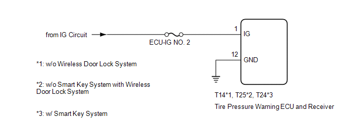
The IG circuit is the power source for the tire pressure warning ECU and receiver.
WIRING DIAGRAM
CAUTION / NOTICE / HINT
NOTICE:
- When replacing the tire pressure warning ECU and receiver, read the transmitter IDs stored in the old ECU using the Techstream and write them down before removal.
- It is necessary to perform initialization (See page
.gif) ) after registration (See page
) of the transmitter IDs into the tire
pressure warning ECU and receiver if the ECU has been replaced.
) after registration (See page
) of the transmitter IDs into the tire
pressure warning ECU and receiver if the ECU has been replaced.
HINT:
Inspect the fuses for circuits related to this system before performing the following procedure.
PROCEDURE
|
1. |
CHECK HARNESS AND CONNECTOR (ECU - BATTERY AND BODYGROUND) |
|
(a) Disconnect the T14*1, T25*2, T24*3 tire pressure warning ECU and receiver connector. |
|
.png)
(b) Measure the voltage according to the value(s) in the table below.
Standard Voltage:
|
Tester Connection |
Switch Condition |
Specified Condition |
|---|---|---|
|
T14-1 (IG) - Body ground*1 T25-1 (IG) - Body ground*2 T24-1 (IG) - Body ground*3 |
Ignition switch ON |
10 to 16 V |
|
Ignition switch off |
Below 1 V |
(c) Measure the resistance according to the value(s) in the table below.
Standard Resistance:
|
Tester Connection |
Condition |
Specified Condition |
|---|---|---|
|
T14-12 (GND) - Body ground*1 T25-12 (GND) - Body ground*2 T24-12 (GND) - Body ground*3 |
Always |
Below 1 Ω |
|
*a |
Front view of wire harness connector (to Tire Pressure Warning ECU and Receiver) |
- *1: w/o Wireless Door Lock System
- *2: w/o Smart Key System with Wireless Door Lock System
- *3: w/ Smart Key System
| OK | .gif) |
REPLACE TIRE PRESSURE WARNING ECU AND RECEIVER |
| NG | |
REPAIR OR REPLACE HARNESS OR CONNECTOR |
 No Signal from Transmitter ID1 (C2121/21-C2124/24,C2181/81-C2184/84)
DESCRIPTION
The tire pressure warning valve and transmitters that are installed in the tire
and wheel assemblies measure the tire pressure of each wheel. The measured values
are transmitted to th ...
 TC and CG Terminal Circuit
DESCRIPTION
Tire pressure warning system DTCs can be checked by connecting terminals 13 (TC)
and 4 (CG) of the DLC3. The DTCs are indicated by blinking the tire pressure warning
light.
WIRING DI ...
Other materials:
Front Axle Hub Bolt
Installation
INSTALLATION
PROCEDURE
1. INSTALL FRONT AXLE HUB BOLT
(a) Install a new hub bolt through the axle hub.
(b) Install the washer plate, as shown in the illustration, through the hub bolt,
and install the hub bolt by tightening the hub nut.
2. INSTALL FRONT DISC
3. INSTALL FRON ...
On-vehicle Inspection
ON-VEHICLE INSPECTION
PROCEDURE
1. INSPECT CURTAIN SHIELD AIRBAG ASSEMBLY (for Vehicle not Involved in Collision)
(a) Perform a Diagnostic System Check (See page
).
(b) With the curtain shield airbag installed on the vehicle, perform
a visual check. If any of the defects mention ...
Headlight Dimmer Relay
Inspection
INSPECTION
PROCEDURE
1. INSPECT HEADLIGHT DIMMER RELAY
(a) Check the resistance.
(1) Measure the resistance according to the value(s) in the table below.
Standard:
Tester Connection
Condition
Specified Condition
...
