Toyota Tacoma (2015-2018) Service Manual: Disassembly
DISASSEMBLY
PROCEDURE
1. REMOVE TELEPHONE MICROPHONE ASSEMBLY
Click here .gif)
2. REMOVE MICROPHONE CASE
HINT:
Use the same procedure for Double Cab.
Click here
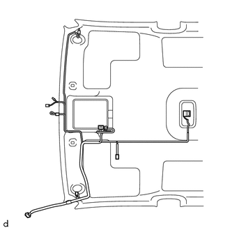
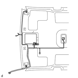
3. REMOVE NO. 1 ROOF WIRE (w/ Vanity Light)
|
(a) w/ EC Mirror: (1) Remove the No. 1 roof wire. |
|
|
(b) w/o EC Mirror: (1) Remove the No. 1 roof wire. |
|
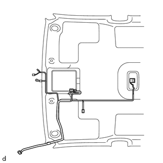
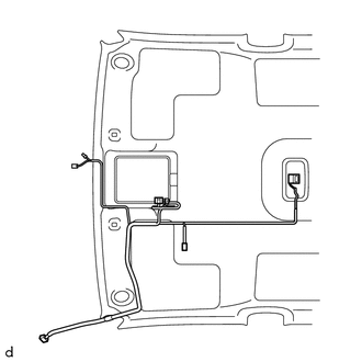
4. REMOVE NO. 1 ROOF WIRE (w/o Vanity Light)
|
(a) w/ EC Mirror: (1) Remove the No. 1 roof wire. |
|
|
(b) w/o EC Mirror: (1) Remove the No. 1 roof wire. |
|
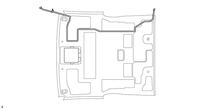
5. REMOVE NO. 2 ANTENNA CORD SUB-ASSEMBLY
(a) Remove the No. 2 antenna cord sub-assembly.
 Components
COMPONENTS
ILLUSTRATION
*A
w/ Rear Seat Assembly
*B
w/o Rear Seat Assembly
*1
BACK PANEL GARNISH HOLE PLUG
*2
...
 Installation
INSTALLATION
PROCEDURE
1. INSTALL ROOF HEADLINING ASSEMBLY
(a) Insert the roof headlining assembly into the vehicle from the door.
NOTICE:
Check that the corners of th ...
Other materials:
Skid Control Buzzer Circuit (C1AA7)
DESCRIPTION
The forward recognition camera operates the pre-collision warning by sending
a buzzer request signal to the skid control buzzer.
If the forward recognition camera detects a malfunction in the skid control buzzer
circuit, it will output DTC C1AA7.
DTC No.
Dete ...
Precaution
PRECAUTION
1. IGNITION SWITCH EXPRESSIONS
(a) The type of ignition switch used on this model differs according to the specifications
of the vehicle. The expressions listed in the table below are used in this section.
Expression
Ignition Switch (Position)
Engine ...
Tire inflation pressure
■ Tire inflation pressure
The recommended cold tire inflation pressure and tire size is displayed on the
tire and loading information label.
Regular Cab and Double Cab models
Access Cab models
■ Inspection and adjustment procedure
1. Tire valve
2. Tire pressure gauge
Re ...
