Toyota Tacoma (2015-2018) Service Manual: Disassembly
DISASSEMBLY
PROCEDURE
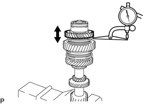
1. INSPECT COUNTERSHAFT REVERSE GEAR THRUST CLEARANCE
|
(a) Using a dial indicator, measure the countershaft reverse gear thrust clearance. Standard clearance: 0.150 to 0.300 mm (0.0060 to 0.0118 in.) If the clearance is outside the specification, replace the countershaft reverse gear, reverse gear bearing inner race or No. 4 transmission clutch hub. HINT: Replace the part or parts determined to be the most likely cause of the problem. |
|
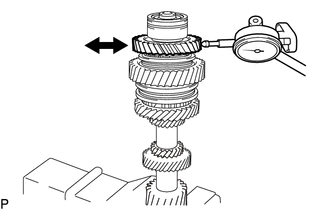
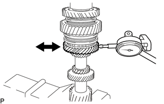
2. INSPECT COUNTERSHAFT REVERSE GEAR RADIAL CLEARANCE
|
(a) Using a dial indicator, measure the countershaft reverse gear radial clearance. Standard clearance: 0.015 to 0.065 mm (0.0006 to 0.0026 in.) If the clearance is outside the specification, replace the countershaft reverse gear, reverse gear bearing inner race or needle roller bearing. HINT: Replace the part or parts determined to be the most likely cause of the problem. |
|
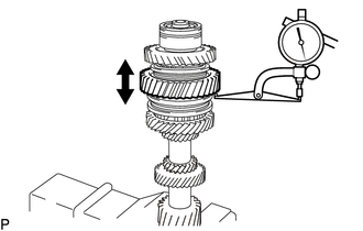
3. INSPECT COUNTERSHAFT 1ST SPEED GEAR THRUST CLEARANCE
|
(a) Using a dial indicator, measure the countershaft 1st speed gear thrust clearance. Standard clearance: 0.150 to 0.480 mm (0.0060 to 0.0188 in.) If the clearance is outside the specification, replace the countershaft 1st speed gear, clutch hub or counter gear. HINT: Replace the part or parts determined to be the most likely cause of the problem. |
|
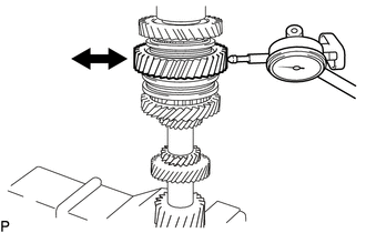
4. INSPECT COUNTERSHAFT 1ST SPEED GEAR RADIAL CLEARANCE
|
(a) Using a dial indicator, measure the countershaft 1st speed gear radial clearance. Standard clearance: 0.015 to 0.067 mm (0.0006 to 0.0026 in.) If the clearance is outside the specification, replace the countershaft 1st speed gear, 1st gear needle roller bearing or shaft. HINT: Replace the part or parts determined to be the most likely cause of the problem. |
|
5. INSPECT COUNTERSHAFT 2ND SPEED GEAR THRUST CLEARANCE
|
(a) Using a dial indicator, measure the countershaft 2nd speed gear thrust clearance. Standard clearance: 0.150 to 0.480 mm (0.0060 to 0.0188 in.) If the clearance is outside the specification, replace the countershaft 2nd speed gear, clutch hub or counter gear. HINT: Replace the part or parts determined to be the most likely cause of the problem. |
|
6. INSPECT COUNTERSHAFT 2ND SPEED GEAR RADIAL CLEARANCE
|
(a) Using a dial indicator, measure the countershaft 2nd speed gear radial clearance. Standard clearance: 0.015 to 0.067 mm (0.0006 to 0.0026 in.) If the clearance is outside the specification, replace the countershaft 2nd speed gear, 2nd gear needle roller bearing or shaft. HINT: Replace the part or parts determined to be the most likely cause of the problem. |
|
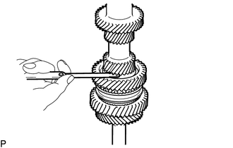
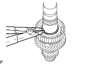
7. REMOVE REAR COUNTER GEAR BEARING SNAP RING
|
(a) Using a snap ring expander, remove the rear counter gear bearing snap ring from the counter gear. |
|
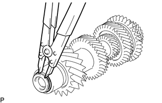
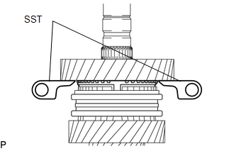
8. REMOVE REAR COUNTER GEAR BEARING OR ROLLER
|
(a) Using SST, remove the rear counter gear bearing or roller (inner races) from the counter gear. SST: 09950-40011 09951-04010 09952-04010 09953-04010 09954-04010 09955-04071 09957-04010 09958-04011 SST: 09950-60010 09951-00320 |
|
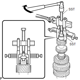
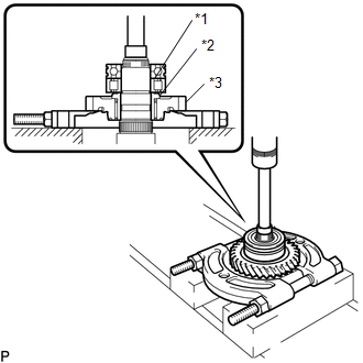
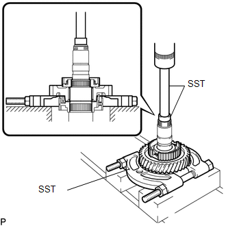
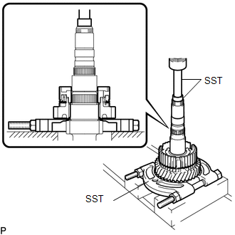
9. REMOVE COUNTERSHAFT REVERSE GEAR
|
(a) Using SST and a press, remove the front counter gear bearing or roller, center countershaft bearing, reverse gear bearing inner race and countershaft reverse gear from the counter gear. Text in Illustration
SST: 09555-55010 SST: 09950-60010 09951-00320 SST: 09950-70010 09951-07100 NOTICE: Support the counter gear by hand so that it does not fall. |
|
10. REMOVE REVERSE GEAR BEARING
(a) Remove the reverse gear bearing from the counter gear.
11. REMOVE REVERSE SHIFT RESTRICT BALL
(a) Remove the reverse shift restrict ball from the counter gear.
12. REMOVE REVERSE SYNCHRONIZER RING
(a) Remove the reverse synchronizer ring from the counter gear.
13. REMOVE NO. 3 SYNCHROMESH SHIFTING KEY SPRING
(a) Remove the No. 3 synchromesh shifting key spring from the counter gear.
14. REMOVE NO. 3 SYNCHROMESH SHIFTING KEY
(a) Remove the 2 No. 3 synchromesh shifting keys from the counter gear.
15. REMOVE NO. 4 TRANSMISSION HUB SLEEVE
(a) Remove the No. 4 transmission hub sleeve from the No. 4 transmission clutch hub.
16. REMOVE NO. 4 TRANSMISSION CLUTCH HUB
(a) Using SST and a press, remove the No. 4 transmission clutch hub and countershaft 1st speed gear from the counter gear.
SST: 09555-55010
SST: 09950-60010
09951-00320
SST: 09950-70010
09951-07100
NOTICE:
- Do not insert SST deep inside the gear, as this may damage the synchronizer ring.
- Use SST in the position shown in the illustration.
17. REMOVE 1ST GEAR NEEDLE ROLLER BEARING
(a) Remove the 1st gear needle roller bearing from the counter gear.
18. REMOVE NO. 1 SYNCHRONIZER RING SET
(a) Remove the No. 1 synchronizer ring set from the counter gear.
19. REMOVE NO. 1 TRANSMISSION HUB SLEEVE
(a) Remove the No. 1 transmission hub sleeve from the No. 1 transmission clutch hub.
20. REMOVE NO. 1 SYNCHROMESH SHIFTING KEY
(a) Remove the 3 No. 1 synchromesh shifting keys from the No. 1 transmission clutch hub.
21. REMOVE NO. 1 CLUTCH HUB SHAFT SNAP RING
|
(a) Using a snap ring expander, remove the No. 1 clutch hub shaft snap ring from the counter gear. |
|
22. REMOVE NO. 1 TRANSMISSION CLUTCH HUB
|
(a) Using SST and a press, remove the countershaft 2nd speed gear, No. 2 synchronizer ring set and No. 1 transmission clutch hub from the counter gear. SST: 09555-55010 SST: 09950-60010 09951-00320 SST: 09950-70010 09951-07100 |
|
23. REMOVE 2ND GEAR NEEDLE ROLLER BEARING
(a) Remove the 2nd gear needle roller bearing from the counter gear.
 Components
COMPONENTS
ILLUSTRATION
ILLUSTRATION
...
 Inspection
INSPECTION
PROCEDURE
1. INSPECT COUNTER GEAR
(a) Using a dial indicator and 2 V-blocks, measure the counter gear runout.
Maximum runout:
0.03 mm (0.00118 in.)
If the runout is ...
Other materials:
Blower Motor Circuit
DESCRIPTION
The blower motor with fan sub-assembly operates according to signals from the
air conditioning amplifier assembly. The blower motor with fan sub-assembly speed
signals are transmitted by changes in the duty ratio.
WIRING DIAGRAM
CAUTION / NOTICE / HINT
NOTICE:
Inspect the fuse ...
Oil Level Sensor
Components
COMPONENTS
ILLUSTRATION
ILLUSTRATION
Inspection
INSPECTION
PROCEDURE
1. INSPECT ENGINE OIL LEVEL SENSOR
(a) Measure the resistance according to the value(s) in the table below.
Standard Resistance:
Tester Connection
Condi ...
Problem Symptoms Table
PROBLEM SYMPTOMS TABLE
HINT:
Use the table below to help determine the cause of problem symptoms. If multiple
suspected areas are listed, the potential causes of the symptoms are listed in order
of probability in the "Suspected Area" column of the table. Check each symptom by
check ...
