Toyota Tacoma (2015-2018) Service Manual: Diagnosis System
DIAGNOSIS SYSTEM
1. DESCRIPTION
The ECU stores trouble codes when malfunctions occur.
The diagnostic system allows for reading of the trouble codes from the DLC3.
Use the Techstream to help diagnose and repair the problem.
2. CHECK DLC3
(a) Check the DLC3 (See page .gif) ).
).
3. INSPECT BATTERY VOLTAGE
(a) Measure the battery voltage.
Standard voltage:
11 to 14 V
If the voltage is below 11 V, recharge or replace the battery.
4. SELF-DIAGNOSTIC MODE
(a) Connect the Techstream to the DLC3.
(b) Turn the engine switch on (IG).
(c) Turn the Techstream on.
(d) Enter the following menus: Body Electrical / Smart Key / Utility / Wireless Door Lock Diagnosis Mode.
(e) Proceed to the next step in accordance with the prompts on the Techstream screen.
HINT:
The electrical key transmitter uses 2 different frequencies alternately for communication. When in self diagnostic mode, one of the channels can be selected or the channels can be automatically switched.
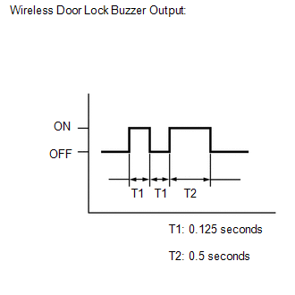
(f) Check that the system has switched to self-diagnostic mode by checking the wireless door lock buzzer output pattern.
(g) Check the diagnostic outputs when the electrical key transmitter sub-assembly switch is held down.
The diagnostic outputs can be checked by the interior light and wireless door lock buzzer patterns.
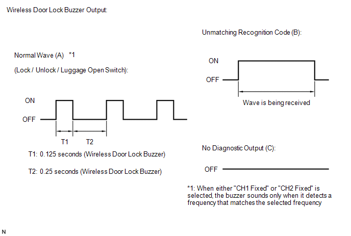 Result
|
Wireless Door Lock Buzzer Output |
Suspected Area |
|---|---|
|
A |
Normal (No malfunction) |
|
B |
Register wireless code |
|
C |
Wave interference or malfunction of a related component |
 Problem Symptoms Table
PROBLEM SYMPTOMS TABLE
HINT:
Use the table below to help determine the cause of problem symptoms.
If multiple suspected areas are listed, the potential causes of the symptoms
are lis ...
 Dtc Check / Clear
DTC CHECK / CLEAR
1. CHECK FOR DTC
HINT:
When using the Techstream with the engine switch off to troubleshoot:
Connect the Techstream to the DLC3 and turn a courtesy light switch on and off
at 1 ...
Other materials:
Gauges and meters
The following gauges, meters and displays illuminate when the engine switch is
in the ON position.
Tachometer
Displays the engine speed in revolutions per minute.
Speedometer
Displays the vehicle speed.
Engine coolant temperature gauge
Displays the engine coolant temperature.
Fuel gauge
...
System Description
SYSTEM DESCRIPTION
1. POWER WINDOW CONTROL SYSTEM DESCRIPTION
(a) The power window control system controls the power window operation using
the power window regulator motors. The main controls of this system are the power
window regulator master switch assembly (mounted on the driver door), po ...
Removal
REMOVAL
CAUTION / NOTICE / HINT
NOTICE:
If one of the camshaft timing gear bolts is already removed, do not remove any
other camshaft timing gear bolts.
PROCEDURE
1. REMOVE NO. 2 ENGINE UNDER COVER SUB-ASSEMBLY (w/ Off Road Package)
2. REMOVE NO. 1 ENGINE UNDER COVER SUB-ASSEMBLY
3. REMOVE ...
