Toyota Tacoma (2015-2018) Service Manual: Components
COMPONENTS
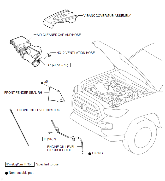
ILLUSTRATION
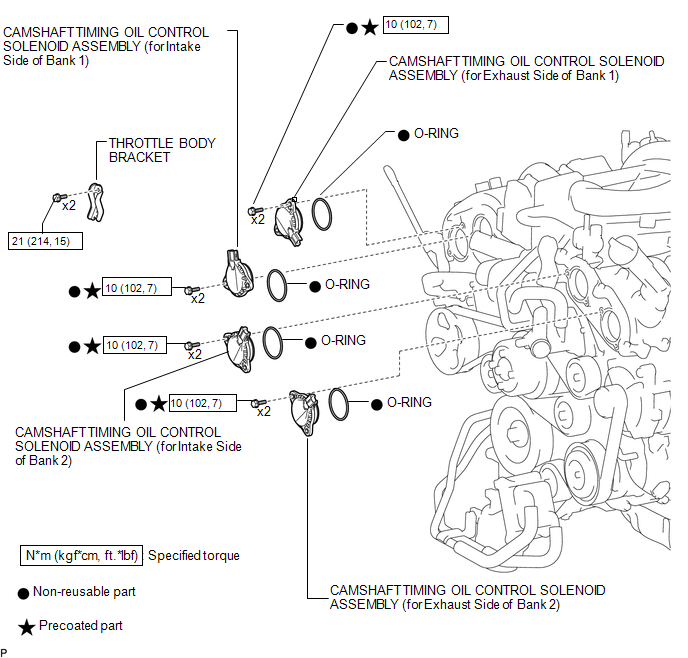
ILLUSTRATION

 On-vehicle Inspection
ON-VEHICLE INSPECTION
PROCEDURE
1. INSPECT CAMSHAFT TIMING OIL CONTROL SOLENOID ASSEMBLY (for Intake Side)
(a) Connect the Techstream to the DLC3.
(b) Start the engine.
(c) Turn the Techstream on ...
Other materials:
Removal
REMOVAL
CAUTION / NOTICE / HINT
PROCEDURE
1. PRECAUTION
CAUTION:
Be sure to read Precaution thoroughly before servicing (See page
).
NOTICE:
After turning the ignition switch off, waiting time may be required before disconnecting
the cable from the negative (-) battery terminal. Therefore ...
Reporting safety defects for U.S. owners
If you believe that your vehicle has a defect which could cause a crash or could
cause injury or death, you should immediately inform the National Highway Traffic
Safety Administration (NHTSA) in addition to notifying Toyota Motor Sales, U.S.A.,
Inc. (Toll-free: 1-800-331-4331).
If NHTSA rece ...
Reassembly
REASSEMBLY
PROCEDURE
1. INSTALL INSTRUMENT PANEL CUSHION
(a) Install a new instrument panel cushion as shown in the illustration.
Text in Illustration
*a
R End
*b
25 to 45 mm
(0.984 to 1.772 in.)
...
