Toyota Tacoma (2015-2018) Service Manual: Components
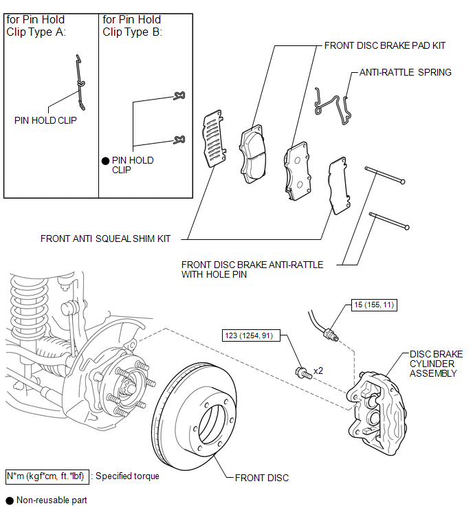
COMPONENTS
ILLUSTRATION
ILLUSTRATION
 Front Brake
...
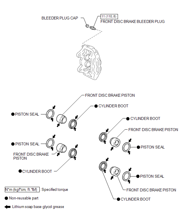
 Disassembly
DISASSEMBLY
PROCEDURE
1. REMOVE CYLINDER BOOT
(a) Using a screwdriver, remove the 4 cylinder boots from the caliper.
2. REMOVE FRONT DISC BRAKE PISTON
(a) Prepare a wooden plate to hold the p ...
Other materials:
Installation
INSTALLATION
PROCEDURE
1. INSTALL WATER INLET WITH THERMOSTAT SUB-ASSEMBLY
(a) Install a new gasket to the water inlet with thermostat sub-assembly.
(b) Install the water inlet with thermostat sub-assembly to the timing chain
cover assembly with the 2 bolts and nut.
Torque:
10 N·m {102 kgf ...
Sleep Operation Failure of Occupant Classification ECU (B1796)
DESCRIPTION
During sleep mode, the occupant detection ECU monitors the condition of each
sensor while the ignition switch is off. In this mode, if the occupant detection
ECU detects an internal malfunction, DTC B1796 is set.
DTC No.
DTC Detections Conditions
Tr ...
SM Solenoid Circuit (C1225,C1468,C1469,C146A,C146B)
DESCRIPTION
These solenoids turn on when signals are received from the skid control ECU (brake
actuator assembly) and they control the pressure acting on the wheel cylinders to
control the braking force.
DTC No.
Detection Item
DTC Detection Condition
...
