Toyota Tacoma (2015-2018) Service Manual: Components
COMPONENTS
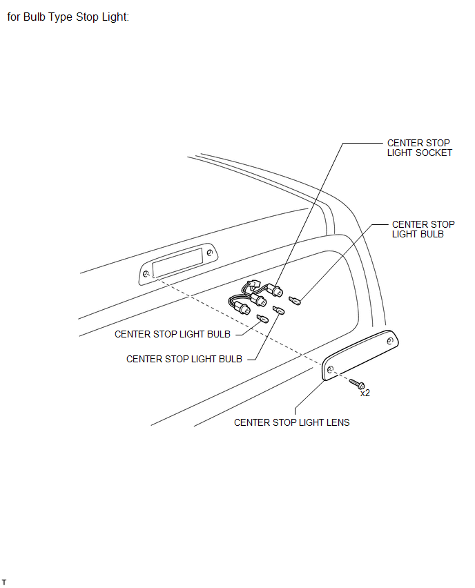
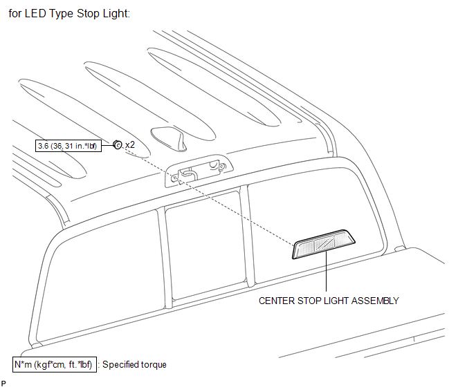
ILLUSTRATION
ILLUSTRATION

 Inspection
INSPECTION
PROCEDURE
1. INSPECT CENTER STOP LIGHT ASSEMBLY (for LED Type Stop Light)
(a) Check the illuminates.
(1) Apply battery voltage to the connector and check the light illuminati ...
Other materials:
Lock Switch Circuit
WIRING DIAGRAM
PROCEDURE
1.
CHECK REAR DIFFERENTIAL LOCK INDICATOR LIGHT
(a) Turn the ignition switch to ON.
(b) for 4WD:
Finish switching to L4.
(c) Check the rear differential lock indicator light.
(d) Press the differential lock switch.
(e) After 60 secon ...
Clearance Warning Buzzer Circuit
DESCRIPTION
This circuit consists of the No. 1 clearance warning buzzer and clearance warning
ECU assembly. An ECU-excited type buzzer is used. The battery voltage supplied through
the buzzer is grounded inside the clearance warning ECU assembly using a pulsed
digital pattern, producing sound ...
Reassembly
REASSEMBLY
PROCEDURE
1. INSTALL GENERATOR DRIVE END FRAME BEARING
(a) Using SST and a press, press in a new generator drive end frame bearing.
SST: 09950-60010
09951-00470
SST: 09950-70010
09951-07100
(b) Fit the ta ...
