Toyota Tacoma (2015-2018) Service Manual: Components
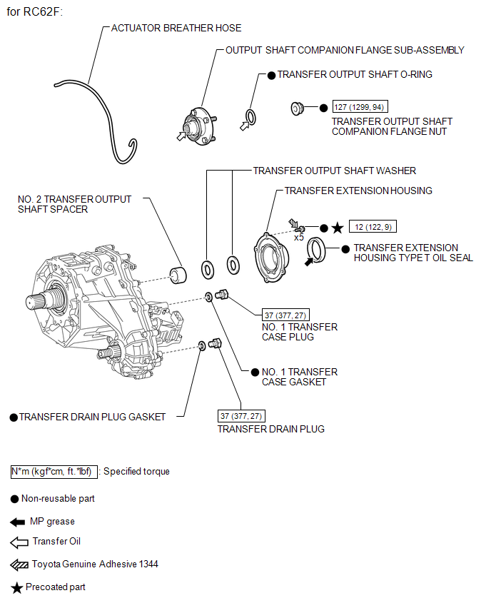
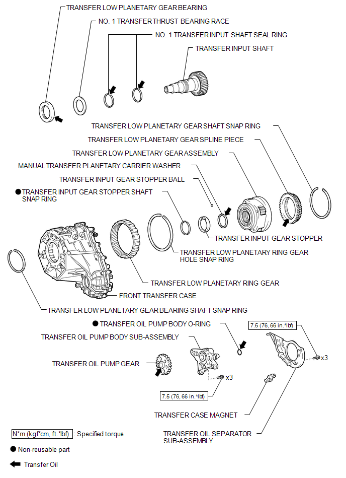
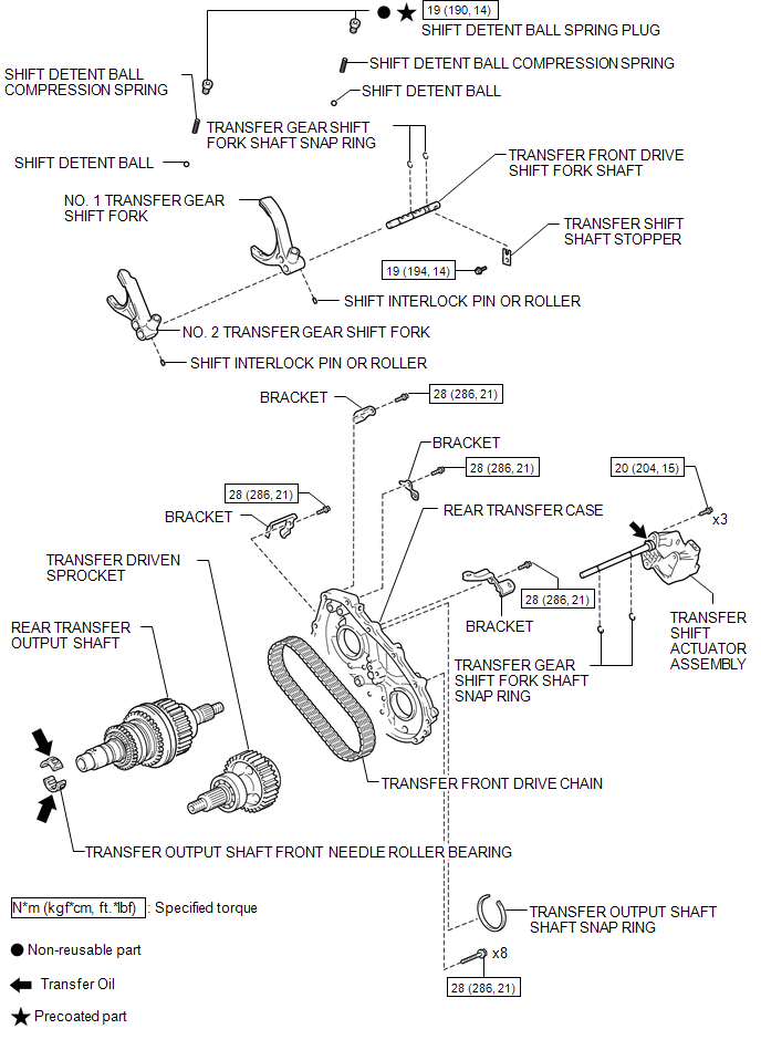
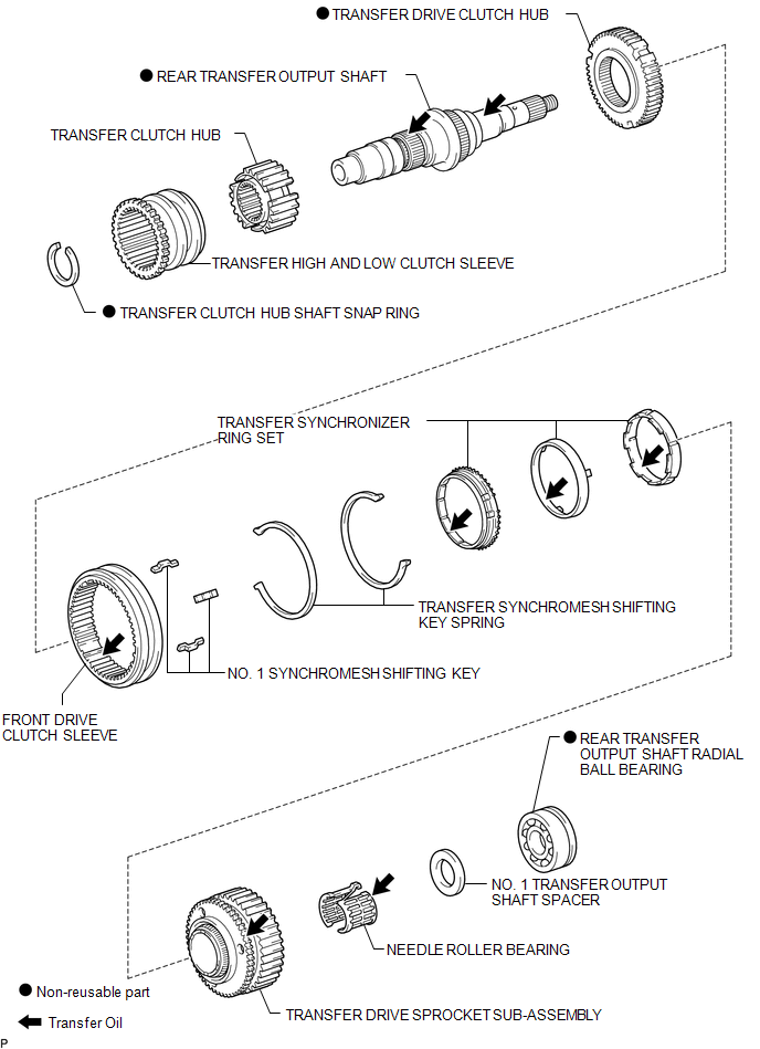
COMPONENTS
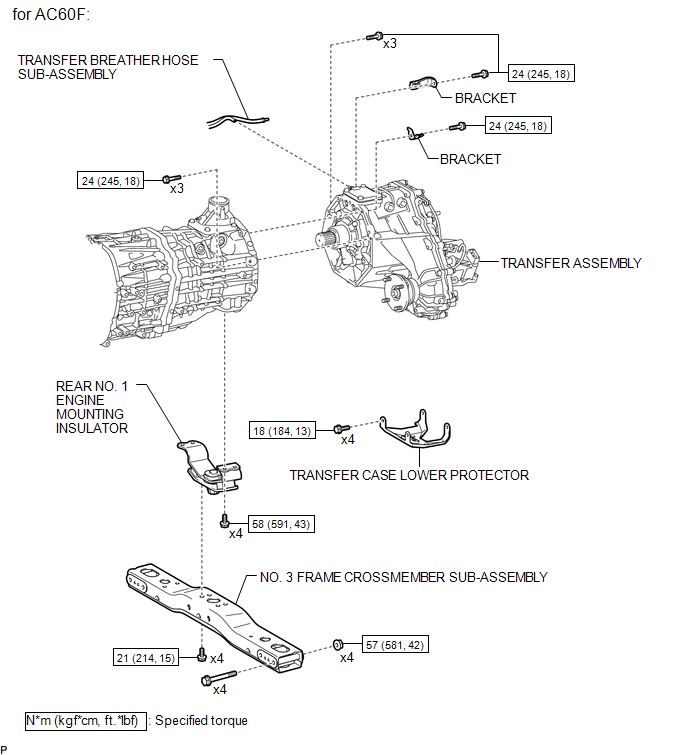
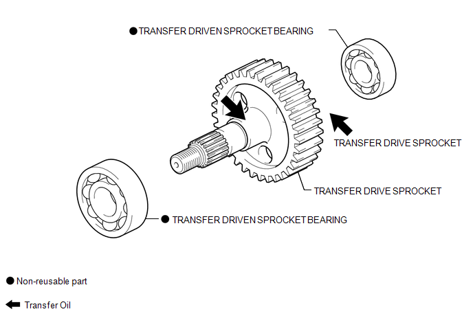
ILLUSTRATION
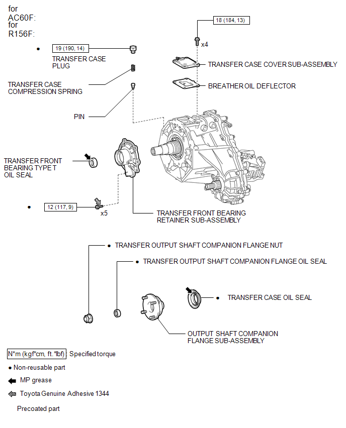
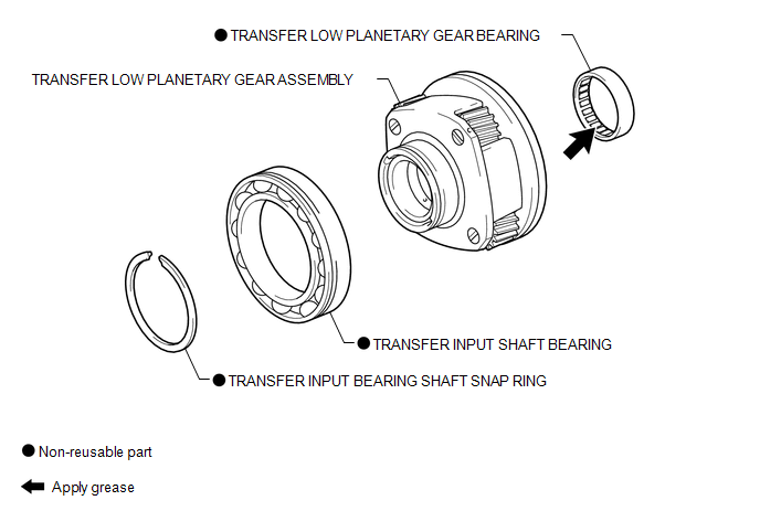
ILLUSTRATION
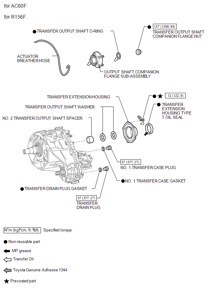
ILLUSTRATION
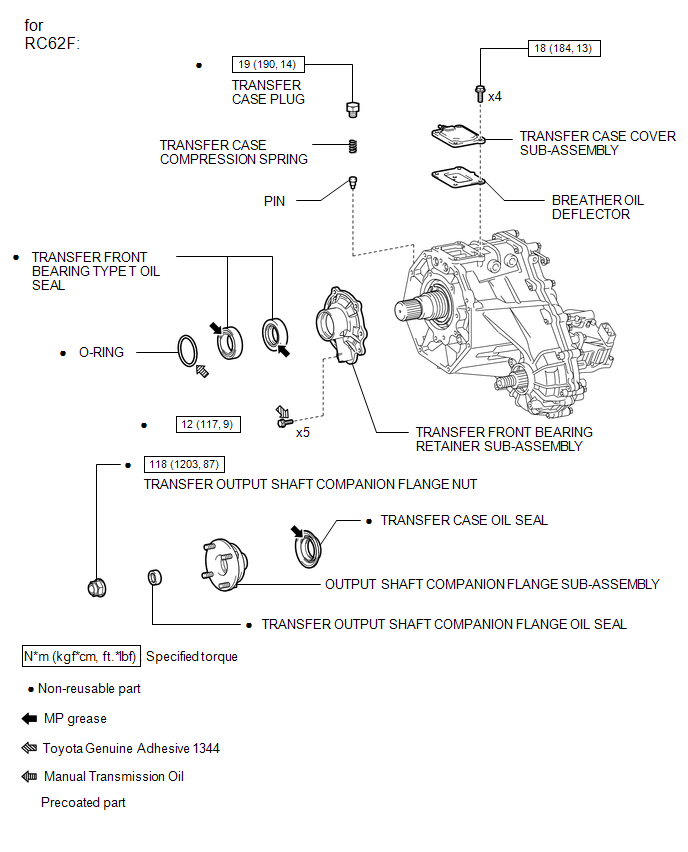
ILLUSTRATION
ILLUSTRATION
ILLUSTRATION
ILLUSTRATION
ILLUSTRATION
ILLUSTRATION
ILLUSTRATION

 Removal
REMOVAL
PROCEDURE
1. DRAIN TRANSFER OIL
2. REMOVE FRONT PROPELLER SHAFT ASSEMBLY
3. REMOVE PROPELLER WITH CENTER BEARING SHAFT ASSEMBLY
4. SUPPORT TRANSMISSION ASSEMBLY
5. REMOVE NO ...
Other materials:
Installing child restraints
Follow the child restraint system manufacturerŌĆÖs instructions. Firmly secure
child restraints to the seats using the LATCH anchors or a seat belt. Attach the
top tether strap when installing a child restraint.
The lap/shoulder belt can be used if your child restraint system is not compatible ...
System Description
SYSTEM DESCRIPTION
1. OUTLINE OF THEFT DETERRENT SYSTEM
The theft deterrent system can be set/canceled by locking/unlocking
the doors using the following operation:
Entry lock operation*1
Wireless lock operation*2
Key-linked lock operation
* ...
Removal
REMOVAL
CAUTION / NOTICE / HINT
HINT:
Use the same procedure for the RH side and LH side.
The following procedure is for the LH side.
When removing the front fender wheel opening moulding or quarter panel
wheel opening moulding, heat the vehicle body and front fender wheel ope ...
